Chapter 2
33
Setting a Password
Follow these steps as you set the user or the supervisor password:
1.
Use the
↑
and
↓
keys to highlight the Set Supervisor Password parameter and press the
Enter
key. The
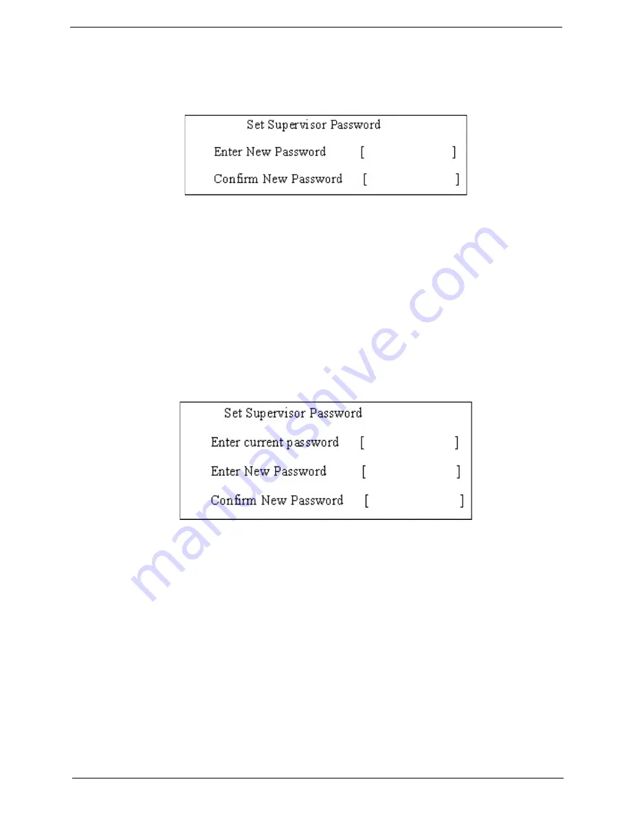
Set Supervisor Password box appears:
2.
Type a password in the “Enter New Password” field. The password length can not exceeds 8
alphanumeric characters (A-Z, a-z, 0-9, not case sensitive). Retype the password in the “Confirm New
Password” field.
IMPORTANT:
Be very careful when typing your password because the characters do not appear on the screen.
3.
Press
Enter
.
After setting the password, the computer sets the User Password parameter to “Set”.
4.
If desired, you can opt to enable the Password on boot parameter.
5.
When you are done, press F10 to save the changes and exit the BIOS Setup Utility.
Removing a Password
Follow these steps:
1.
Use the
↑
and
↓
keys to highlight the Set Supervisor Password parameter and press the
Enter
key. The
Set Password box appears:
2.
Type the current password in the Enter Current Password field and press
Enter
.
3.
Press
Enter
twice
without
typing anything in the Enter New Password and Confirm New Password fields.
The computer then sets the Supervisor Password parameter to “Clear”.
4.
When you have changed the settings, press
u
to save the changes and exit the BIOS Setup Utility.
Содержание Aspire 5530 Series
Страница 6: ...VI ...
Страница 14: ...4 Chapter 1 System Block Diagram ...
Страница 36: ...26 Chapter 1 ...
Страница 62: ...52 Chapter 3 6 Remove the HDD cover as shown 7 Remove the WLAN cover as shown ...
Страница 83: ...Chapter 3 73 6 Turn the upper cover over The upper cover appears as follows ...
Страница 104: ...94 Chapter 3 7 Lift the Thermal Module clear of the Mainboard ...
Страница 110: ...100 Chapter 3 6 Disconnect the left and right Inverter board cables as shown ...
Страница 124: ...114 Chapter 3 3 Replace the RJ 11 cable in its housing ...
Страница 135: ...Chapter 3 125 2 Replace the bracket as shown 3 Replace the single securing screw ...
Страница 138: ...128 Chapter 3 2 Connect the seven cables on the mainboard as shown B C D E F G A ...
Страница 144: ...134 Chapter 3 7 Replace the adhesive strip to secure the cable 8 Replace bracket and secure with provided screw ...
Страница 150: ...140 Chapter 3 ...
Страница 178: ...168 Chapter 5 ...
Страница 193: ...Chapter 6 183 ...
Страница 196: ...Appendix A 186 ...
Страница 202: ...192 Appendix B ...
Страница 204: ...194 Appendix C ...
Страница 207: ...197 Windows 2000 Environment Test 188 Wireless Function Failure 154 WLAN Board 54 ...
Страница 208: ...198 ...


