74
Chapter 3
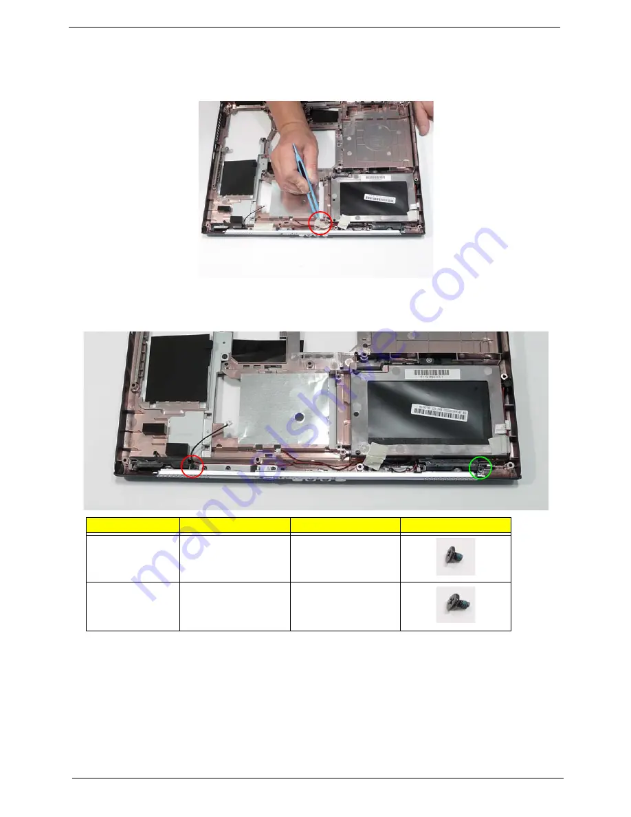
Removing the Speaker Module
1.
See “Removing the Mainboard” on page 71.
2.
Remove the adhesive tape from the speaker cable.
3.
Remove the two screws from the speaker modules.
NOTE:
The left and right speaker module securing screws differ slightly in length. Ensure the correct screw is
used for each speaker.
Step
Size
Quantity
Screw Type
Left Speaker
Module
(red callout)
M2.5*3
1
Right Speaker
Module
(green callout)
M2.5*6
1
Содержание Aspire 5515
Страница 6: ...VI ...
Страница 10: ...X Table of Contents ...
Страница 31: ...Chapter 1 21 ...
Страница 51: ...40 Chapter 2 ...
Страница 56: ...Chapter 3 45 3 Carefully open the memory cover 4 Remove the HDD cover as shown ...
Страница 59: ...48 Chapter 3 7 Press down on the locking catch to release the ODD cover and remove ...
Страница 72: ...Chapter 3 61 5 Turn the computer over Disconnect the power and camera cables from the mainboard ...
Страница 74: ...Chapter 3 63 8 Carefully remove the LCD module from the chassis ...
Страница 104: ...Chapter 3 93 18 Reconnect the left side of the spring as shown ...
Страница 107: ...96 Chapter 3 2 Replace the four screws and the rubber screw caps provided ...
Страница 112: ...Chapter 3 101 7 Replace the six securing screws in the mainboard ...
Страница 115: ...104 Chapter 3 ...
Страница 122: ...Chapter 3 111 2 Replace the four screws in numerical order from screw 1 to screw 4 to secure the Thermal Module 1 2 3 4 ...
Страница 129: ...118 Chapter 3 ...
Страница 155: ...144 Chapter 5 ...
Страница 173: ...162 Appendix B Microsoft Windows Vista Environment Test Vendor Type Description Adapter Test Audio Codec ...
Страница 175: ...164 Appendix C ...


