Chapter 6
153
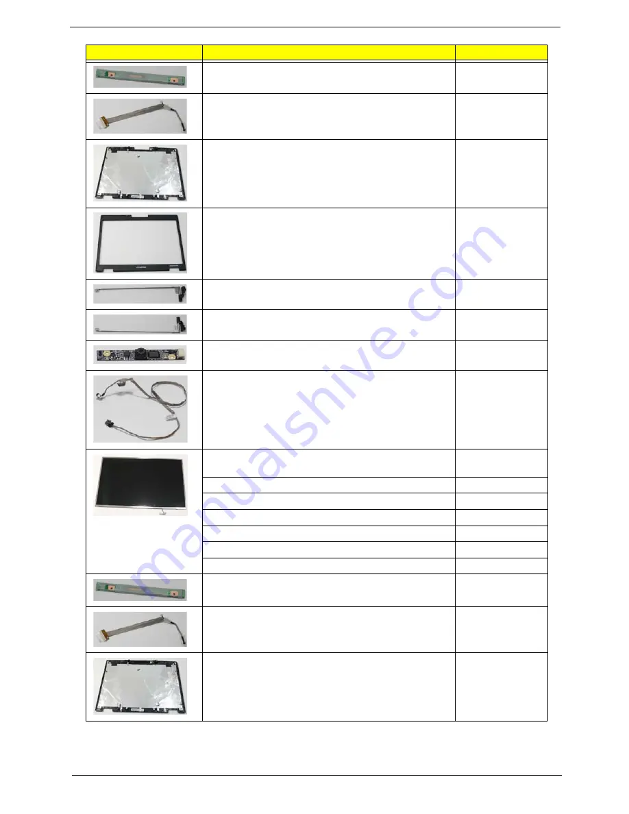
INVERTER BOARD
19.N2702.001
LCD CABLE
50.N2702.003
LCD COVER FOR W/CCD
60.N2602.001
LCD BEZEL FOR W/CCD
60.N2602.002
LCD BRACKET-R FOR W/CCD
33.N2702.004
LCD BRACKET-L FOR W/CCD
33.N2702.005
CAMERA 0.3M
57.N2602.001
CMOS CABLE
50.N2602.001
ASSY LCD MODULE 15.4 IN. WXGA GLARE W/
ANTENNA
6M.N2702.003
LCD PANEL G 15.4 WXGA AU B154EW08 V1(3A) S01
LK.15405.034
LCD PANEL G 15.4 WXGA AU B154EW08 V1 3A S03
TBD
LCD PANEL G 15.4 WXGA CMO N154I3-L03
LK.1540D.022
LCD PANEL G 15.4 WXGA LG LP154WX4-TLB4
LK.15408.029
LCD PANEL G 15.4 WXGA SEC LTN154AT01-A01
TBD
LCD PANEL G 15.4 WXGA SEC LTN154AT01-A04
TBD
INVERTER BOARD
19.N2702.001
LCD CABLE
50.N2702.003
LCD COVER FOR W/O CCD
60.N2702.003
Category
Description
Acer Part No.
Содержание Aspire 5515
Страница 6: ...VI ...
Страница 10: ...X Table of Contents ...
Страница 31: ...Chapter 1 21 ...
Страница 51: ...40 Chapter 2 ...
Страница 56: ...Chapter 3 45 3 Carefully open the memory cover 4 Remove the HDD cover as shown ...
Страница 59: ...48 Chapter 3 7 Press down on the locking catch to release the ODD cover and remove ...
Страница 72: ...Chapter 3 61 5 Turn the computer over Disconnect the power and camera cables from the mainboard ...
Страница 74: ...Chapter 3 63 8 Carefully remove the LCD module from the chassis ...
Страница 104: ...Chapter 3 93 18 Reconnect the left side of the spring as shown ...
Страница 107: ...96 Chapter 3 2 Replace the four screws and the rubber screw caps provided ...
Страница 112: ...Chapter 3 101 7 Replace the six securing screws in the mainboard ...
Страница 115: ...104 Chapter 3 ...
Страница 122: ...Chapter 3 111 2 Replace the four screws in numerical order from screw 1 to screw 4 to secure the Thermal Module 1 2 3 4 ...
Страница 129: ...118 Chapter 3 ...
Страница 155: ...144 Chapter 5 ...
Страница 173: ...162 Appendix B Microsoft Windows Vista Environment Test Vendor Type Description Adapter Test Audio Codec ...
Страница 175: ...164 Appendix C ...


