


14
Chapter 1
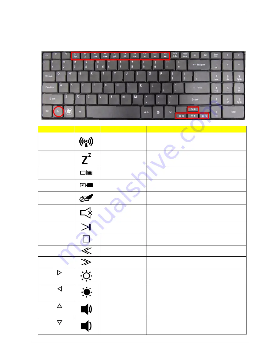
Hot Keys
The computer employs hotkeys or key combinations to access most of the computer’s controls like screen
brightness, volume output and the BIOS utility.
To activate hot keys, press and hold the <
Fn>
key before pressing the other key in the hotkey combination.
Hotkey
Icon
Function
Description
<Fn> + <F3>
Communication key
Enables/disables the computer’s communication
devices. (Communication devices may vary by
configuration.)
<Fn> + <F4>
Sleep
Puts the computer in Sleep mode.
<Fn> + <F5>
Display toggle
Switches display output between the display
screen, external monitor (if connected) and both.
<Fn> + <F6>
Screen blank
Turns the display screen backlight off to save
power. Press any key to return.
<Fn> + <F7>
Touchpad toggle
Turns the internal touchpad on and off.
<Fn> + <F8>
Speaker toggle
Turns the speakers on and off.
<Fn> +<F9>
Play/Pause
Play or pause a selected media file.
<Fn> + <F10>
Stop
Stop playing the selected media file.
<Fn> +<F11>
Previous
Return to the previous media file.
<Fn> + <F12>
Next
Jump to the next media file.
<Fn> + <
>
Brightness up
Increases the screen brightness.
<Fn> + <
>
Brightness down
Decreases the screen brightness.
<Fn> + <
>
Volume up
Increases the sound volume.
<Fn> + <
>
Volume down
Decreases the sound volume.
Содержание Aspire 5334
Страница 6: ...VI ...
Страница 10: ...X Table of Contents ...
Страница 15: ...Chapter 1 5 System Block Diagram ...
Страница 52: ...42 Chapter 2 ...
Страница 74: ...64 Chapter 3 14 Lift the LCD Module clear of the Upper Cover ...
Страница 81: ...Chapter 3 71 5 Lift the Speaker clear of the Upper Cover left side first as shown ...
Страница 87: ...Chapter 3 77 4 Using both hands lift the Thermal Module clear of the Mainboard ...
Страница 102: ...92 Chapter 3 9 The Antennas and cables appear as shown when correctly installed ...
Страница 107: ...Chapter 3 97 2 Replace the four 4 screws and screw caps provided ...
Страница 112: ...102 Chapter 3 5 Replace the FFC and press down as indicated to secure it to the Upper Cover ...
Страница 114: ...104 Chapter 3 2 Replace the two 2 screws to secure the board to the Upper Cover ...
Страница 117: ...Chapter 3 107 6 Connect and lock the power board FFC cable as shown 7 Connect the speaker cable as shown ...
Страница 128: ...118 Chapter 3 ...
Страница 132: ...122 Chapter 3 ...
Страница 159: ...Chapter 5 149 Clear CMOS Jumper Item Description J1 Clear CMOS Jumper J1 ...
Страница 244: ...234 Appendix C ...
Страница 248: ...238 ...


