


Chapter 1
7
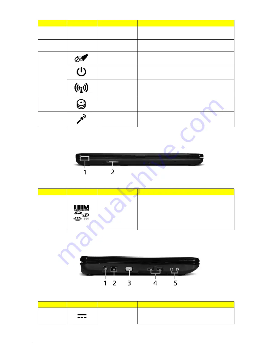
Closed Front View
Aspire 5734Z model only
Left View
7
Click buttons (left
and right)
The left and right buttons function like the left
and right mouse buttons.
8
Palmrest
Comfortable support area for your hands when
you use the computer.
9
Touchpad toggle
Turns the internal touchpad on and off.
Power button
Turns the computer on and off.
Communication
key
Enables/disables the computer’s
communication devices. (Communication
devices may vary by configuration.)
10
HDD indicator
Indicates when the hard disk drive is active.
11
Microphone
Internal microphone for sound recording.
No.
Icon
Item
Description
1
5-in-1 card
reader
Accepts Secure Digital (SD), MultiMediaCard
(MMC), Memory Stick (MS), Memory Stick
PRO (MS PRO), xDPicture Card (xD).
NOTE:
Push to remove/install the card.
Only one card can operate at any
given time.
No.
Icon
Item
Description
1
DC-in jack
Connects to an AC adapter
No.
Icon
Item
Description
Содержание Aspire 5334
Страница 6: ...VI ...
Страница 10: ...X Table of Contents ...
Страница 15: ...Chapter 1 5 System Block Diagram ...
Страница 52: ...42 Chapter 2 ...
Страница 74: ...64 Chapter 3 14 Lift the LCD Module clear of the Upper Cover ...
Страница 81: ...Chapter 3 71 5 Lift the Speaker clear of the Upper Cover left side first as shown ...
Страница 87: ...Chapter 3 77 4 Using both hands lift the Thermal Module clear of the Mainboard ...
Страница 102: ...92 Chapter 3 9 The Antennas and cables appear as shown when correctly installed ...
Страница 107: ...Chapter 3 97 2 Replace the four 4 screws and screw caps provided ...
Страница 112: ...102 Chapter 3 5 Replace the FFC and press down as indicated to secure it to the Upper Cover ...
Страница 114: ...104 Chapter 3 2 Replace the two 2 screws to secure the board to the Upper Cover ...
Страница 117: ...Chapter 3 107 6 Connect and lock the power board FFC cable as shown 7 Connect the speaker cable as shown ...
Страница 128: ...118 Chapter 3 ...
Страница 132: ...122 Chapter 3 ...
Страница 159: ...Chapter 5 149 Clear CMOS Jumper Item Description J1 Clear CMOS Jumper J1 ...
Страница 244: ...234 Appendix C ...
Страница 248: ...238 ...


