


12
Chapter 1
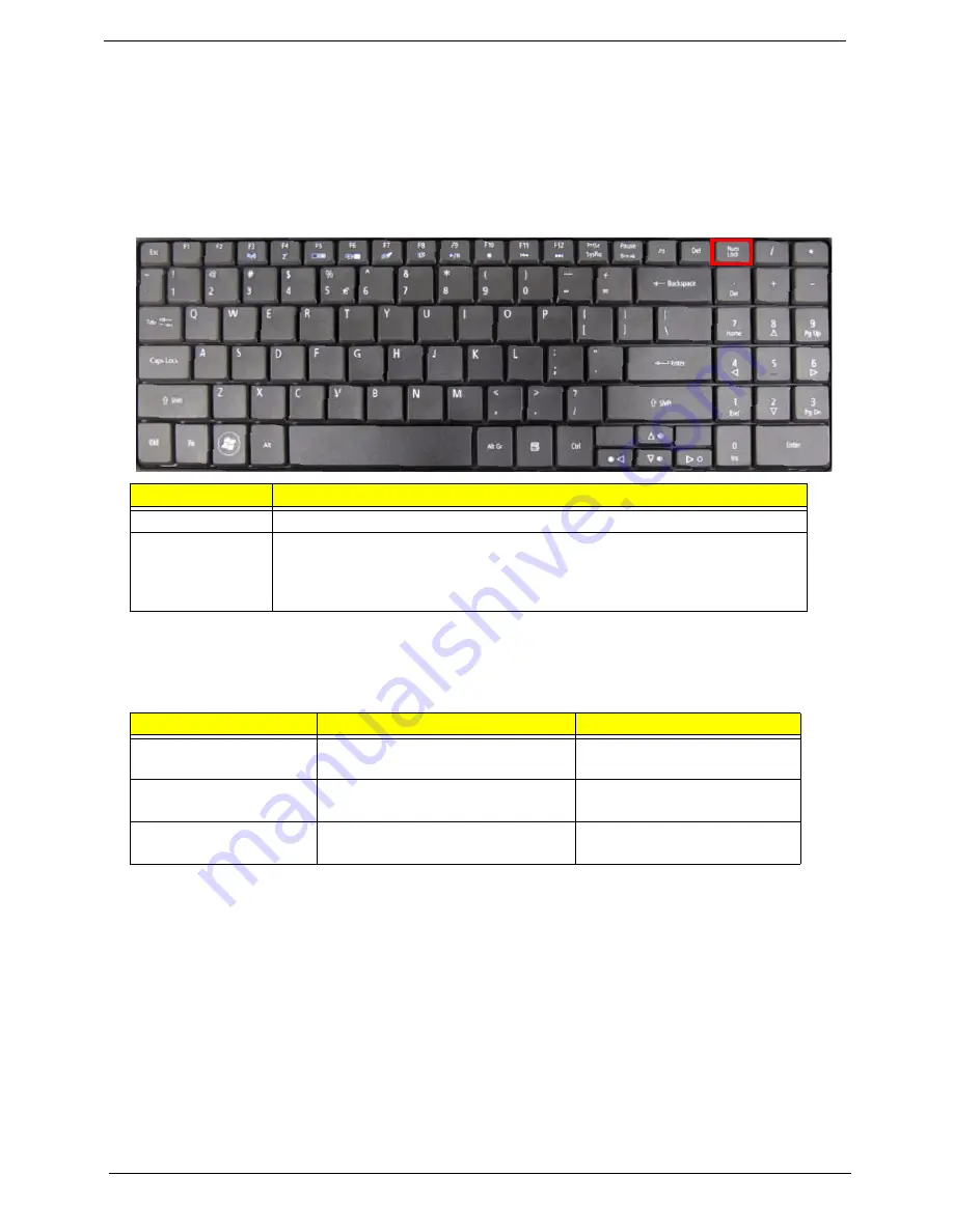
Using the Keyboard
The keyboard has full-sized keys and an embedded numeric keypad, separate cursor, lock, Windows, function
and special keys.
Lock Keys and embedded numeric keypad
The keyboard has two lock keys which you can toggle on and off.
The embedded numeric keypad functions like a desktop numeric keypad. It is indicated by small characters
located on the upper right corner of the keycaps. To simplify the keyboard legend, cursor-control key symbols
are not printed on the keys.
Lock key
Description
Caps Lock
When Caps Lock is on, all alphabetic characters typed are in uppercase.
Num Lock
When Num Lock is on, the embedded keypad is in numeric mode. The keys
function as a calculator (complete with the arithmetic ope, -, *, and /). Use
this mode when you need to do a lot of numeric data entry. A better solution
would be to connect an external keypad.
Desired access
Num Lock on
Num Lock off
Number keys on
embedded keypad
Type numbers in a normal manner.
Cursor-control keys on
embedded keypad
Hold
<Shift>
while using cursor-
control keys.
Hold
<Fn>
while using cursor-
control keys.
Main keyboard keys
Hold
<Fn>
while typing letters on
embedded keypad.
Type the letters in a normal
manner.
Содержание Aspire 5334
Страница 6: ...VI ...
Страница 10: ...X Table of Contents ...
Страница 15: ...Chapter 1 5 System Block Diagram ...
Страница 52: ...42 Chapter 2 ...
Страница 74: ...64 Chapter 3 14 Lift the LCD Module clear of the Upper Cover ...
Страница 81: ...Chapter 3 71 5 Lift the Speaker clear of the Upper Cover left side first as shown ...
Страница 87: ...Chapter 3 77 4 Using both hands lift the Thermal Module clear of the Mainboard ...
Страница 102: ...92 Chapter 3 9 The Antennas and cables appear as shown when correctly installed ...
Страница 107: ...Chapter 3 97 2 Replace the four 4 screws and screw caps provided ...
Страница 112: ...102 Chapter 3 5 Replace the FFC and press down as indicated to secure it to the Upper Cover ...
Страница 114: ...104 Chapter 3 2 Replace the two 2 screws to secure the board to the Upper Cover ...
Страница 117: ...Chapter 3 107 6 Connect and lock the power board FFC cable as shown 7 Connect the speaker cable as shown ...
Страница 128: ...118 Chapter 3 ...
Страница 132: ...122 Chapter 3 ...
Страница 159: ...Chapter 5 149 Clear CMOS Jumper Item Description J1 Clear CMOS Jumper J1 ...
Страница 244: ...234 Appendix C ...
Страница 248: ...238 ...


