Acer Aspire 5332 Series Скачать руководство пользователя страница 58

48

Chapter 3

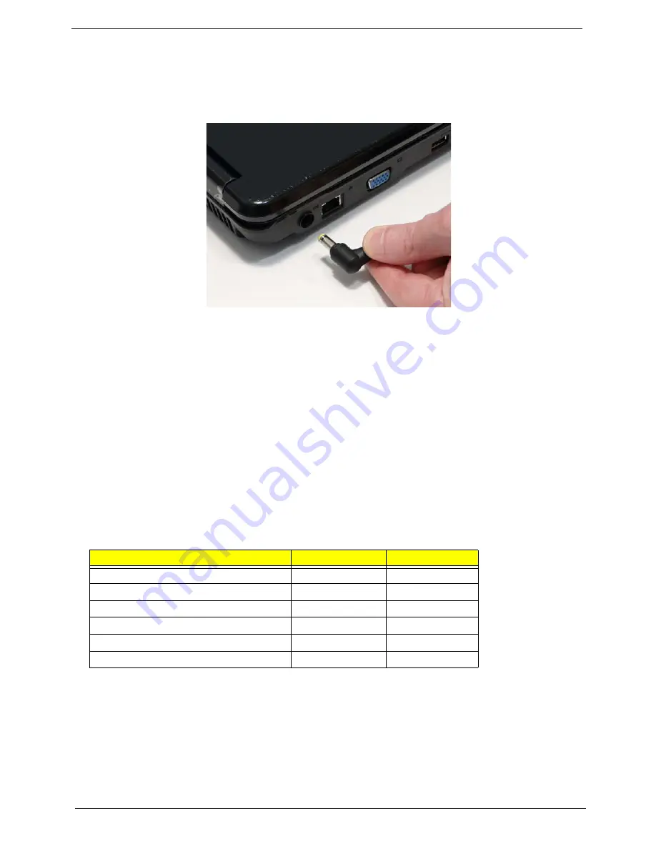
Pre-disassembly Instructions

Before proceeding with the disassembly procedure, make sure that you do the following:

1.

Turn off the power to the system and all peripherals.

2.

Unplug the AC adapter and all power and signal cables from the system.

3.

Place the system on a flat, stable surface. 

4.

Remove the battery pack.

Disassembly Process

IMPORTANT: 

The LCD Module cannot be disassembled outside of factory conditions. If any part of the LCD 

Module is faulty, such as the camera, antenna or LCD panel, the whole module must be replaced. 

The disassembly process is divided into the following stages:

External module disassembly

Main unit disassembly

LCD module disassembly

The flowcharts provided in the succeeding disassembly sections illustrate the entire disassembly sequence. 
Observe the order of the sequence to avoid damage to any of the hardware components. For example, if you 
want to remove the mainboard, you must first remove the keyboard, then disassemble the inside assembly 
frame in that order.

Main Screw List 

Screw

Quantity

Part Number

SCREW M2.48D 4.0L K 5.5D 0.8T ZKNL

1

86.N2802.001

SCREW M2.48D 6.0L K 5.5D 0.8T ZKNL

6

86.N2802.002

SCREW M2.45D 8.0L K 5.5D 0.8T ZKNL

30

86.N2802.003

SCREW M1.98D 3.0L K 4.6D 0.8T ZKNL

4

86.N2802.004

SCREW M M 3.0D 3.0L K 4.9D NI +

4

86.N2802.005

SCREW M M 2.5D 3.2L K 6D NI +

17

86.N2802.006

Содержание Aspire 5332 Series

Страница 1: ...Aspire 5732Z 5332 Service Guide PRINTED IN TAIWAN Service guide files and updates are available on the ACER CSD web for more information please refer to http csd acer com tw...

Страница 2: ...II Revision History Please refer to the table below for the updates made on Aspire 5732Z 5332 service guides Date Chapter Updates...

Страница 3: ...ect to the contents hereof and specifically disclaims any warranties of merchantability or fitness for any particular purpose Any Acer Incorporated software described in this manual is sold or license...

Страница 4: ...bits and pieces of additional information related to the current topic WARNING Alerts you to any damage that might result from doing or not doing specific actions CAUTION Gives precautionary measures...

Страница 5: ...NOT be covered in this generic service guide In such cases please contact your regional offices or the responsible personnel channel to provide you with further technical details 2 Please note WHEN OR...

Страница 6: ...VI...

Страница 7: ...el BIOS 26 Information 26 Main 27 Advanced 28 Security 30 Power 33 Boot 35 Exit 36 BIOS Flash Utilities 37 DOS Flash Utility 38 WinFlash Utility 40 Remove HDD BIOS Password Utilities 41 Machine Disass...

Страница 8: ...CD Bezel 100 Main Module Reassembly Procedure 102 Replacing the CPU 102 Replacing the CPU Fan 103 Replacing the Thermal Module 103 Replacing the Mainboard 104 Replacing the TouchPad Bracket 105 Replac...

Страница 9: ...0_PORT 146 Jumper and Connector Locations 147 Top View 147 Bottom View 148 Power Board 149 Clearing Password Check and BIOS Recovery 150 Clearing Password Check 150 Clear CMOS Jumper 150 BIOS Recovery...

Страница 10: ...X Table of Contents...

Страница 11: ...Link 802 11b g Acer InviLink Nplify 802 11b g Draft N System Memory Dual channel support Up to 2 GB of DDR2 667 MHz memory upgradeable to 4 GB using two soDIMM modules Display 15 6 WXGA HD 720p 1366x7...

Страница 12: ...Ethernet Wake on LAN ready Privacy control BIOS user supervisor HDD passwords Kensington lock slot Power subsystem ACPI 3 0 48 8 W 4400 mAh 3 pin 65 W AC adapter ENERGY STAR Special keys and controls...

Страница 13: ...Chapter 1 3 Humidity non condensing Operating 20 to 80 Non operating 20 to 80...

Страница 14: ...ory BUS DDRII BGA 676 HD Au dio page 4 page 7 8 9 10 11 12 13 Intel ICH9 M Thermal Sensor page 14 1 5 page 19 20 21 22 page 30 ENE KB926 D2 LCD C onn Bluetooth Conn 3 3V 24 576M Hz 48Mhz Phone Jack x2...

Страница 15: ...tal Display LCD displays computer output 3 Touchpad toggle Turns the internal touchpad on and off Power button Turns the computer on and off Wireless LAN communication button indicator Enables disable...

Страница 16: ...tes when the hard disk drive is active No Icon Item Description 1 Power1 Indicates the computer s power status Battery1 Indicates the computer s battery status 1 Charging The light shows amber when th...

Страница 17: ...ter 2 Ethernet RJ 45 port Connects to an Ethernet 10 100 based network 2 External display VGA port Connects to a display device e g external monitor LCD projector 4 USB 2 0 ports Connect to USB 2 0 de...

Страница 18: ...ed off Note Insert a paper clip into the emergency eject hole to eject the optical drive tray when the computer is off 5 Kensington lock slot Connects to a Kensington compatible computer security lock...

Страница 19: ...Houses the computer s hard disk secured with screws 5 Memory compartment Houses the computer s main memory 5 Ventilation slots and cooling fan Enable the computer to stay cool even after prolonged us...

Страница 20: ...ing The light shows amber when the battery is charging 2 Fully charged The light shows green when in AC mode Icon Function Description Power Indicates the computer s power status Battery Indicates the...

Страница 21: ...Pad keep it and your fingers dry and clean The TouchPad is sensitive to finger movement hence the lighter the touch the better the response Tapping too hard will not increase the TouchPad s responsive...

Страница 22: ...ercase Num Lock Fn F11 When Num Lock is on the embedded keypad is in numeric mode The keys function as a calculator complete with the arithmetic operators and Use this mode when you need to do a lot o...

Страница 23: ...ork domain M Minimizes all windows R Open the Run dialog box T Cycle through programs on the taskbar U Open Ease of Access Center X Open Windows Mobility Center BREAK Display the System Properties dia...

Страница 24: ...powering Technology Fn F3 Bluetooth Enables disables the Bluetooth function only for certain models Fn F4 Sleep Puts the computer in Sleep mode Fn F5 Display toggle Switches display output between the...

Страница 25: ...t Gr and then press the 5 key at the upper center of the keyboard NOTE Note Some fonts and software do not support the Euro symbol Please refer to www microsoft com typography faq faq12 htm for more i...

Страница 26: ...ltiple windows on the same screen To access this function please go to Start All Programs and click on Acer GridVista You may choose any one of the four display settings indicated below Double vertica...

Страница 27: ...667 800 1066MHz Item CPU Speed Cores Bus Speed Mfg Tech Cache Size Package Core Voltage Acer P N T1600 1 66 GHz 2 667 MHz 65 nm 1 M PGA 1 075V 1 175V KC 16001 CMT T1700 1 83 GHz 2 667 MHz 65 nm 1 M PG...

Страница 28: ...ed Step support C1 C2 C3 C4 and S3 S4 for mobile CPU DMI utility for BIOS serial number configurable asset tag Supports PXE Supports Y2K solution Supports Win Flash Wake on LAN from S3 Wake on LAN for...

Страница 29: ...B 2048MB 1024MB 2048MB 3072MB 2048MB 0MB 2048MB 2048MB 512MB 2560MB 2048MB 1024MB 3072MB 2048MB 2048MB 4096MB Item Specification LAN Chipset Atheros integrated onboard gigabit ethernet Package 48 pin...

Страница 30: ...Buffer size 8 MB 8 MB 8 MB 8 MB Interface SATA SATA SATA SATA Internal transfer rate Mbits sec max 352 395 952 typical 850 Mbits s maximum I O data transfer rate Mbytes sec max 150 300 300 maximum DC...

Страница 31: ...i Session Video CD CD Audio Disc Mixed mode CD ROM disc data and audio CD Extra CD Text CD R Conforming to Orange Book Part 2 read write CD RW Conforming to Orange Book Part 3 read write DVD Read DVD...

Страница 32: ...kage configuration 3S2P Item Specification Vendor model name CMO N156B3 L02 Screen Diagonal mm 396 2 Display Area mm 344 23 x 193 54 Display resolution pixels 1366 x 768 Pixel Pitch 0 252 Display Mode...

Страница 33: ...Chapter 1 23 Card Reader Item Specification Part Name RealTek RT5159 Package 5 in 1 card reader General Features PCI E interface Push push type Dummy card...

Страница 34: ...24 Chapter 1...

Страница 35: ...nge boot device without entering BIOS SETUP Utility Navigating the BIOS Utility There are six menu options Information Main Advanced Security Boot and Exit Follow these instructions To choose a menu u...

Страница 36: ...s field displays the manufacturer of this system UUID Universally Unique Identifier UUID is an identifier standard used in software construction standardized by the Open Software Foundation OSF as par...

Страница 37: ...disables Boot Menu during POST Option Enabled or Enabled D2D Recovery Enables disables D2D Recovery function The function allows the user to create a hidden partition on hard disc drive to store opera...

Страница 38: ...IDE Configuration menu IDE Controller HDC Configure as AHCI Option ROM Support SATA Port 0 1 4 5 HotPlug Channel 1 to 4 Master and Slave Item Specific Help Configures Boot Settings F1 ESC Help Exit Se...

Страница 39: ...k ASPM Control Automatic ASPM PCI Latency Timer VT d iTPM ACPI Table Features Control Enter the ACPI Table Features Control menu FACP C2 Latency Value FACP C3 Latency Value FACP RTC S4 Wakeup APIC IO...

Страница 40: ...et the user password When user password is set this password protects the BIOS Setup Utility from unauthorized access The user can enter Setup menu only and does not have right to change the value of...

Страница 41: ...er to Set 4 If desired you can opt to enable the Password on boot parameter 5 When you are done press F10 to save the changes and exit the BIOS Setup Utility Removing a Password Follow these steps 1 U...

Страница 42: ...en you are done press F10 to save the changes and exit the BIOS Setup Utility If the verification is OK the screen will display as following The password setting is complete after the user presses Ent...

Страница 43: ...ontrol menu P States IST Boot performance mode Thermal Mode CMP Support Use XD capability VT Support SMRR Support C States Enhanced C States C State Pop Up Mode C State Pop Down Mode C4 Exit Timing Mo...

Страница 44: ...le wake up when the system power is off and a PCI Power Management Enable wake up event occurs N A Wake on Modem Ring Disable or Enable wake up when the system power is off and a modem attached to the...

Страница 45: ...st or F6 to move it up the list Press Esc to escape the menu F1 ESC Help Exit Select Item Select Menu Change Values Select SubMenu Enter F9 F10 Setup Default Save and Exit Boot priority order 1 IDE0 W...

Страница 46: ...all SETUP item Discard Changes Load previous values from CMOS for all SETUP items Save Changes Save Setup Data to CMOS Item Specific Help Exit System Setup and save your changes to CMOS F1 ESC Help Ex...

Страница 47: ...Diskette before you use the Phlash utility NOTE Do not install memory related drivers XMS EMS DPMI when you use the Phlash NOTE Please use the AC adaptor power supply when you run the Phlash utility...

Страница 48: ...ess F5 to move it down the list or F6 to move it up the list Press Esc to escape the menu F1 ESC Help Exit Select Item Select Menu Change Values Select SubMenu Enter F9 F10 Setup Default Save and Exit...

Страница 49: ...e message Please do not remove AC Power Source displays NOTE If the AC power is not connected the following message displays Plug in the AC power to continue 5 Flash is complete when the message Flash...

Страница 50: ...40 Chapter 2 WinFlash Utility Perform the following steps to use the WinFlash Utility 1 Double click the WinFlash executable 2 Click OK to begin the update A progress screen displays...

Страница 51: ...is displayed select the Enter Unlock Password option on the screen 2 An Encode key is generated for unlocking utilities Note down this key 3 Execute the UnlockHD EXE file to create the unlock code in...

Страница 52: ...tal instrument to short the J1 jumper Cleaning BIOS Passwords To clean the User or Supervisor passwords perform the following steps 1 From a DOS prompt execute clnpwd exe 2 Press 1 or 2 to clean the d...

Страница 53: ...nged without accessing the BIOS To use Boot Sequence Selector perform the following steps 1 Enter into DOS 2 Execute BS exe to display the usage screen 3 Select the desired boot sequence by entering t...

Страница 54: ...al number to eeprom max 22 characters dmitools wu xxxx Write uuid to eeprom dmitools wa xxxx Write asset tag to eeprom max 32 characters The following examples show the commands and the corresponding...

Страница 55: ...the EEPROM under DOS mode 1 Use a text editor for example Notepad to open the MAC CFG file You can see the MAC CFG contents as below 2 In DOS mode run the MAC BAT file to write MAC values to eeprom Wr...

Страница 56: ...46 Chapter 2...

Страница 57: ...oting Disassembly Requirements To disassemble the computer you need the following tools Wrist grounding strap and conductive mat for preventing electrostatic discharge Flat screwdriver Philips screwdr...

Страница 58: ...ided into the following stages External module disassembly Main unit disassembly LCD module disassembly The flowcharts provided in the succeeding disassembly sections illustrate the entire disassembly...

Страница 59: ...mponents that need to be removed during servicing For example if you want to remove the keyboard you must first remove the switch board Screw List Step Screw Quantity Part No Lower Covers M2 5 8 3 86...

Страница 60: ...moving the Battery Pack 1 Turn computer over Slide the battery lock in the direction shown 2 Slide and hold the battery release latch to the release position 1 then lift out the battery pack from the...

Страница 61: ...Chapter 3 51 Removing the SD Dummy Card 1 Push the SD dummy card all the way in to eject it 2 Pull it out from the slot...

Страница 62: ...ng the Battery Pack on page 50 2 Remove the three 3 screws securing the Memory and HDD Covers 3 Remove the HDD cover by the top edge as shown 4 Carefully open the Memory Cover Step Size Quantity Screw...

Страница 63: ...on page 50 2 Remove one 1 screw securing the ODD module 3 Insert a suitable tool into the access slot in the battery bay as shown Gently lever the ODD module out of the chassis 4 Pull the optical driv...

Страница 64: ...e the two 2 screws securing the ODD bracket and remove the ODD bracket from the optical disk drive module 6 Pull the top edge of the bezel downward and clear of the device Step Size Quantity Screw Typ...

Страница 65: ...DIMM Modules 1 See Removing the Lower Covers on page 52 2 Push out the release latches on both sides of the DIMM socket to release the DIMM module 3 Remove the DIMM module 4 Repeat steps for the seco...

Страница 66: ...See Removing the Lower Covers on page 52 2 Remove the adhesive tape securing the Antenna cables in place 3 Disconnect the antenna cables from the WLAN Board NOTE Cable placement is Black to the MAIN...

Страница 67: ...emove the two 2 screws to release the WLAN Board 5 Detach the WLAN Board from the WLAN socket NOTE When reattaching the antennas ensure the cables are tucked into the chassis to prevent damage Step Si...

Страница 68: ...the Lower Covers on page 52 2 Using the pull slide the HDD Module in the direction of the arrow to disconnect the interface 3 Lift the HDD Module clear of the HDD bay NOTE To prevent damage to device...

Страница 69: ...Chapter 3 59 4 Remove the four 4 screws two on each side securing the hard disk to the carrier 5 Remove the HDD from the carrier Step Size Quantity Screw Type HDD Carrier M3 3 4...

Страница 70: ...N2802 006 Right Speaker Module M2 3 1 86 N2802 006 TouchPad Bracket M2 3 2 86 N2802 006 Mainboard M2 5 4 1 86 N2802 001 Thermal Module M1 98 3 0 4 86 N2802 004 CPU Fan M2 3 3 86 N2802 006 Remove Main...

Страница 71: ...Switch Cover 1 See Removing the Battery Pack on page 50 2 Turn the computer over Press down the and keys on the right side of the Keyboard to expose the cutout Insert a suitable plastic tool or finge...

Страница 72: ...61 2 Pry up the centre of the Keyboard and rotate it upward away from the Upper Cover 3 Turn the keyboard over on to the TouchPad area to expose the FFC connector 4 Open the locking latch and disconne...

Страница 73: ...on page 62 2 Turn the computer over Remove the two 2 securing screws from the bottom of the chassis 3 Remove the Antenna Cables from the cable channel as shown Ensure that the cables are free from al...

Страница 74: ...les completely through the chassis 5 Disconnect the LCD cable from the Mainboard and remove the cable from the cable channel 6 Remove the white Antenna cable from the cable channel Ensure that the cab...

Страница 75: ...le channel as shown Ensure that the cable is completely free of the retaining clips all the way to the hinge well 9 Open the LCD Panel to the full extent to expose the Hinge Covers 10 Press the left s...

Страница 76: ...e four 4 securing screws two each side from the LCD module 13 Remove the left and right screw covers from on top of the hinges 14 Lift the LCD Module clear of the Upper Cover Step Size Quantity Screw...

Страница 77: ...ving the LCD Module on page 63 2 Turn the computer over Remove the eleven 11 screws on the bottom panel 3 Turn the computer over Remove the three screw caps at the rear of the Upper Cover as shown Ste...

Страница 78: ...68 Chapter 3 4 Disconnect the following four cables from the Mainboard labeled A B C and D A B C D...

Страница 79: ...the connectors NOTE Use the pull tabs on FFCs whenever available to prevent damage 5 Disconnect A as shown 6 Disconnect C as shown 7 Release the locking latch on B and remove the FFC cable as shown 8...

Страница 80: ...10 Starting at the rear left side of the cover pry apart the Upper and Lower Covers as shown Work along the back edge of the casing to the right as shown then lift the Upper Cover clear of the Lower...

Страница 81: ...he Upper Cover on page 67 2 Locate the Power Board on the Upper Cover as shown 3 Remove the two 2 screws securing the Power Board to the Upper Cover 4 Lift the Power Board clear of the Upper Cover as...

Страница 82: ...e Removing the Upper Cover on page 67 2 Locate the Left Speaker Module on the Upper Cover as shown 3 Remove the adhesive tape from the Speaker cable 4 Remove the Speaker cable from the cable channel E...

Страница 83: ...hapter 3 73 5 Remove the one 1 securing screw from the Left Speaker Module 6 Lift the Speaker clear of the Upper Cover left side first as shown Step Size Quantity Screw Type Left Speaker Module M2 3 1...

Страница 84: ...e 67 2 Locate the Right Speaker Module on the Upper Cover as shown 3 Turn the Upper Cover over and remove the Right Speaker Module cable from the cable channel Ensure that the cable is free from all c...

Страница 85: ...apter 3 75 5 Remove the one 1 securing screw from the Right Speaker Module 6 Lift the Speaker clear of the Upper Cover right side first as shown Step Size Quantity Screw Type Right Speaker Module M2 3...

Страница 86: ...e removed individually To replace the TouchPad Board replace the entire Upper Cover 1 See Removing the Upper Cover on page 67 2 Lift the FFC to detach the adhesive securing the cable to the Upper Cove...

Страница 87: ...3 77 4 Remove the two 2 screws from TouchPad bracket 5 Lift the rear edge of the TouchPad bracket first to clear the securing clips and remove it as shown Step Size Quantity Screw Type TouchPad Bracke...

Страница 88: ...e Removing the Upper Cover on page 67 2 Remove the one 1 securing screw from the Mainboard 3 Lift the mainboard from the chassis internal edge first and place it on a clean dust free surface Step Size...

Страница 89: ...79 Removing the RTC Battery IMPORTANT Follow local regulations for disposal of all batteries The RTC Battery is soldered to the Mainboard To replace the battery solder the new battery to the connecti...

Страница 90: ...he Lower Covers on page 52 2 Remove the four securing screws in reverse numerical order from screw 4 to screw 1 from the Thermal Module 3 Using both hands lift the Thermal Module clear of the Mainboar...

Страница 91: ...ing the CPU Fan 1 See Removing the Thermal Module on page 80 2 Disconnect the Fan cable from the Mainboard as shown 3 Remove the three 3 securing screws from the Fan Module Step Size Quantity Screw Ty...

Страница 92: ...82 Chapter 3 4 Lift the CPU Fan clear of the Mainboard as shown...

Страница 93: ...te If they are damaged the CPU may malfunction Place the CPU on a clean dry surface when it is not installed 1 See Removing the Thermal Module on page 80 2 Using a flat bladed screw driver rotate the...

Страница 94: ...Step Screw Quantity Part No LCD Bezel M2 5 6 4 86 N2802 002 LCD Panel M2 5 6 2 86 N2802 002 LCD Brackets M2 3 6 86 N2802 006 Remove LCD Panel Remove LCD Bezel Remove LCD FPC Cable Remove LCD Panel fr...

Страница 95: ...ting from the bottom edge of the bezel pry the bezel upwards and away from the panel Work along the right side toward the top of the bezel prying the covers apart Continue along the top edge and down...

Страница 96: ...Chapter 3 Removing the Camera Module 1 See Removing the LCD Bezel on page 85 2 Locate the Camera Module at the top of the LCD Module and disconnect the camera cable 3 Remove the Camera from the modul...

Страница 97: ...the Camera Module on page 86 2 Remove the two 2 securing screws from the LCD Panel 3 Remove the adhesive strip holding the cables in place 4 Remove the Camera cable cluster from the LCD Module as show...

Страница 98: ...88 Chapter 3 5 Lift the LCD Panel clear of the module...

Страница 99: ...FPC Cable 1 See Removing the LCD Panel on page 87 2 Remove the six 6 securing screws three on each side from the LCD Panel brackets 3 Remove the LCD brackets by pulling away from the LCD Panel Step Si...

Страница 100: ...LCD panel over to expose the rear Lift the adhesive protector and disconnect the cable from the LCD Panel 5 Lift the cable as shown to pull free the adhesive strip securing it in place 6 Lift the FPC...

Страница 101: ...he adhesive strips holding the left antenna cable in place Ensure the cable is free from obstructions 3 Remove the cable from the cable channel Ensure that the cable is free from all cable clips and a...

Страница 102: ...r of the cover 6 Remove the adhesive strips holding the right antenna cable in place Ensure the cable is free from obstructions 7 Remove the cable from the cable channel Ensure that the cable is free...

Страница 103: ...Chapter 3 93 8 Remove the adhesive tape securing the right Antenna to the LCD Module 9 Lift the right Antenna clear of the cover...

Страница 104: ...that the locating pins on the Antenna are correctly seated 2 Replace the adhesive strip to secure the Antenna in place 3 Lay the cable down the side of the LCD Module using all available clips and adh...

Страница 105: ...na are correctly seated 6 Replace the adhesive strip to secure the Antenna in place 7 Run the cable down the side of the LCD Module using all available clips and adhesive 8 Run the cable along the cab...

Страница 106: ...96 Chapter 3 9 The Antennas and cables appear as shown when correctly installed...

Страница 107: ...place 3 Run the cable along the back of the panel and press down as indicated to secure the cable in place 4 Run the cable across the back of the panel as shown and press down as indicated to secure t...

Страница 108: ...eplace the six 6 screws three on each side in the brackets as shown 6 Place the LCD Panel in the LCD Module top edge first and secure the LCD cable with adhesive tape IMPORTANT Ensure that the LCD pow...

Страница 109: ...Replacing the Camera Module 7 Replace the Camera cable cluster in the LCD Module 8 Secure the LCD module with the two securing screws 1 Place the camera in the LCD Module 2 Connect the cable to the c...

Страница 110: ...placing the LCD Bezel 1 Replace the bezel and press down until there are no gaps between the bezel and the LCD Module IMPORTANT Ensure that the LCD cables pass through the hinge wells and are not trap...

Страница 111: ...Chapter 3 101 2 Replace the four 4 screws and screw caps provided...

Страница 112: ...ocator that must be positioned corresponding to the marker on the CPU socket 1 Place the CPU into the CPU socket as shown taking note of the Pin1 locator 2 Using a flat bladed screw driver rotate the...

Страница 113: ...1 Align the screw holes on the CPU Fan and Mainboard and replace the Fan 2 Replace the three 3 screws to secure the Fan to the Mainboard 3 Connect the Fan power cable to the Mainboard connector 1 Remo...

Страница 114: ...e the four 4 securing screws in numerical order from screw 1 to screw 4 to secure the Thermal Module in place 1 Ensure that the Mainboard is face up the CPU is not visible Place the Mainboard in the c...

Страница 115: ...uchPad bracket top edge first to engage the securing clips 2 Press the bracket down to engage the securing clips 3 Replace the two 2 screws to secure the TouchPad Bracket to the Upper Cover 4 Replace...

Страница 116: ...106 Chapter 3 5 Replace the FFC and press down as indicated to adhere it to the Upper Cover...

Страница 117: ...e left side of the module is seated correctly in the securing clip 2 Replace the one 1 screw to secure the module in place 3 Pass the cable through the Upper Cover as shown 4 Turn the Upper Cover over...

Страница 118: ...n Ensure that the right side of the module is seated correctly in the securing clip 2 Replace the one 1 screw to secure the module in place 3 Run the cable along the cable channel using all available...

Страница 119: ...ver 1 Slide the Power Board in to the Upper Cover front edge first to engage the securing clip 2 Press the board down to locate the securing pin 3 Replace the two 2 screws to secure the board to the U...

Страница 120: ...110 Chapter 3 2 Press down around the edges to secure it in place 3 Replace the nine 9 screws in the Upper Cover as shown...

Страница 121: ...Chapter 3 111 4 Replace the three 3 screw caps as shown 5 Connect the following cables to the Mainboard A B C D...

Страница 122: ...12 Chapter 3 6 Connect A as shown 7 Connect C as shown 8 Connect B and close the locking latch to secure the cable in place 9 Connect D and close the locking latch to secure the cable in place A C B D...

Страница 123: ...s on the LCD Module and Upper Cover and replace the LCD Module 2 The left and right screw covers are shaped differently Ensure that the correct cover is used 3 Replace the left screw cover as shown En...

Страница 124: ...Cover 5 Replace the four 4 screws securing the LCD Module to the Upper Cover 6 Ensure that the Hinge Covers are replaced correctly Identify the rear edge of the covers by the two securing clips 7 Ali...

Страница 125: ...aining clips 10 Replace the adhesive strip to secure the cable in place 11 Run the white Antenna cable along the cable channel as shown using all available retaining clips 12 Run the LCD cable along t...

Страница 126: ...and pass the Antenna cables through the chassis 15 The Upper Cover appears as shown when the Antenna and LCD cables are correctly installed 16 Turn the computer over Run the Antenna cables along the c...

Страница 127: ...Chapter 3 117 17 Replace the two 2 screws securing the LCD Module to the Lower Cover...

Страница 128: ...to the Mainboard and close the locking latch to secure the cable in place 2 Turn the Keyboard over and insert it front edge first into the chassis NOTE Ensure that the six locating tabs are correctly...

Страница 129: ...the Hard Disk Drive Module 1 Place the Switch Cover left side first on to the Upper Cover 2 Press down as indicated to snap the Switch Cover into place 1 Place the HDD in the HDD carrier 2 Replace the...

Страница 130: ...120 Chapter 3 3 Insert the HDD as indicated and lower it into place 4 Slide the HDD in the direction of the arrow to connect the interface...

Страница 131: ...2 Antenna cables to the module NOTE The black cable connects to the upper terminal MAIN and the white cable to the lower terminal MAIN 4 After connecting the cables to the terminals secure the cables...

Страница 132: ...e ODD bracket with the two 2 screws 3 Push the ODD Module into the ODD bay until it is flush with the casing 4 Replace the one 1 screw to secure the Module 1 Replace the Memory Cover as shown 2 Replac...

Страница 133: ...ng the SD Dummy Card 3 Replace the three 3 screws to secure the covers in place 1 Insert the SD Dummy Card into the slot as shown 2 Push until the card clicks into place and is flush with the casing M...

Страница 134: ...Replacing the Battery 1 Slide and hold the battery release latch to the release position 1 insert the battery pack and press down 2 2 Slide the battery lock in the direction shown to secure the batter...

Страница 135: ...by running the diagnostic test or by repeating the same operation 3 Use the following table with the verified symptom to determine which page to go to 4 If the Issue is still not resolved see Online...

Страница 136: ...y extension cables between the computer and the outlet 3 Remove any surge protectors between the computer and the electrical outlet Plug the computer directly into a known good electrical outlet 4 Dis...

Страница 137: ...power see Power On Issue on page 126 3 Drain any stored power by removing the power cable and battery and holding down the power button for 10 seconds Reconnect the power and reboot the computer 4 Con...

Страница 138: ...e Resolution slider to the desired resolution e Click Apply and check the display Readjust if necessary 6 Roll back the video driver to the previous version if updated 7 Remove and reinstall the video...

Страница 139: ...e following actions one at a time to correct the problem Do not replace a non defective FRUs Built In Keyboard Failure If the built in Keyboard fails perform the following actions one at a time to cor...

Страница 140: ...perform the following actions one at a time to correct the problem Do not replace a non defective FRUs Internal Speaker Failure If the internal Speakers fail perform the following actions one at a tim...

Страница 141: ...Speaker Setup Follow the onscreen prompts to configure the speakers 8 Remove and recently installed hardware or software 9 Restore system and file settings from a known good date using System Restore...

Страница 142: ...ate and resolve issues with the computer i When complete click Finish If an issue is discovered follow the onscreen information to resolve the problem 4 Run the Windows Memory Diagnostic Tool For more...

Страница 143: ...eaks up or jumps Optical drive not found or not active Not shown in My Computer or the BIOS setup LED does not flash when the computer starts up The tray does not eject Access failure screen displays...

Страница 144: ...Movie fields select the desired player from the drop down menu 5 Check that the Regional Code is correct for the selected media IMPORTANT Region can only be changed a limited number of times After Cha...

Страница 145: ...rboard and cable connections c Try an alternate cable if available If the drive works with the new cable the original cable should be replaced 4 Reseat the drive ensuring and all cables are connected...

Страница 146: ...ls perform the following actions one at a time to correct the problem Do not replace a non defective FRUs Thermal Unit Failure If the Thermal Unit fails perform the following actions one at a time to...

Страница 147: ...is not fixed repeat the preceding steps and select an earlier time and date 9 Run the Event Viewer to check the events log for errors For more information see Windows Help and Support 10 Roll back th...

Страница 148: ...er a short circuit is suspected or whether the system is inoperative Follow these procedures to isolate the failing FRU do not isolate non defective FRU NOTE Verify that all attached devices are suppo...

Страница 149: ...AS latency between the DIMMS and the MCH 0x09 Determine the memory frequency and CAS latency to program 0x10 Determine the smallest common TRAS for all DIMMs 0x11 Determine the smallest common TRP for...

Страница 150: ...0x50 Get the root bridge handle 0x51 Notify pci bus driver starts to program the resource 0x58 Reset the host controller 0x5A IdeBus begin initialization 0x70 Simple Text Output Protocol Functions VG...

Страница 151: ...Chapter 4 141 0xF8 Report that ExitBootServices has been called 0xF9 Runtime driver set virtual address map Code Description...

Страница 152: ...LE 0x0D PEI_PLATFORM_STAGE2 0x0E PEI_SB_SMBUS_ARP_DISABLED 0x0F PEI_HOST_TO_SYSTEM 0x10 PEI_MEMORY_INIT 0x11 PEI_S3_RESUME 0x12 PEI_CLOCK_GEN 0x13 PEI_OP_PRESENCE 0x14 PEI_TPM_TCG 0x15 PEI_FIND_FV 0x1...

Страница 153: ...0x4B SB_SM_BUS 0x4C ISA_ACPI_DRIVER 0x4D ISA_BUS 0x4E ISA_SERIAL 0x4F IDE_BUS 0x50 PCI_BUS 0x51 BOOT_PRIORITY 0x52 FVB_SERVICE 0x53 ACPI_PLATFORM 0x54 PCI_HOT_PLUG 0x55 DXE_PLATFORM 0x56 PLATFORM_IDE...

Страница 154: ...ILITY 0x77 FW_BLOCK_SERVICE 0x78 USB_LEGACY_PLATFORM 0x79 GRAPHICS_CONSOLE 0x7A TERMINAL 0x7B DATA_HUB_STD_ERR 0x7C FAT 0x7D PARTITION 0x7E ENGLISH 0x7F FRENCH 0x80 HII_DATABASE 0x81 SETUP_BROWSER 0x8...

Страница 155: ...DXE_OEM_SERVICE 0xA5 DXE_EVENT_LOG 0xA6 DXE_ SECURITY_HDD_PASSWORD_SERVICE 0xA7 DXE_LAN_ASF_INIT 0xA8 DXE_BUS_PCI_SERIAL 0xA9 DXE_LAN_IDER_CONTROLLER 0xAA DXE_LAN_AMT 0xAB DXE_ SECURITY_SYSTEM_PASSWO...

Страница 156: ...y It first displays the check point code followed by a delay the high order byte another delay and then the low order byte of the error It repeats this sequence continuously Code Description 0xC0 SMM_...

Страница 157: ...em Description JLVDS1 LCD Connector JP14 Power B Connector JSPK1 Speaker Left Connector JSPK2 Speaker Right Connector JKB1 Internal Keyboard Connector JTP1 Touch Pad Connector U11 South Bridge SW4 Tou...

Страница 158: ...Fan Connector JUSB1 USB Connector JUSB2 USB Connector JMIC1 MIC In Jack JHP1 Head Phone Jack JSATA2 HDD Connector U23 North Bridge JCPU1 CPU Socket JREAD1 Card Reader Socket PJP2 Battery Connector JD...

Страница 159: ...pter 5 149 Power Board ITEM DESCRIPTION U1 Lid Switch SW1 TP Lock Button SW2 ON OFF Button SW3 Wireless Button LED1 ON OFF LED LED3 Media LED LED4 Num LED LED5 Wireless LED LED6 Caps LED LED7 TP Lock...

Страница 160: ...assword by the following steps 1 Power Off the system and remove HDD AC and Battery from the machine 2 Open the back cover of the machine and remove the Modem Board see Removing the DIMM Modules on pa...

Страница 161: ...IOS to enter a special BIOS block called Boot Block Steps for BIOS Recovery from USB Storage Before doing this prepare the Crisis USB key The Crisis USB key could be made by executing the Crisis Disk...

Страница 162: ...152 Chapter 5...

Страница 163: ...r reasons a part number change is made it will not be noted on the printed Service Guide For ACER AUTHORIZED SERVICE PROVIDERS your Acer office may have a DIFFERENT part number code from those given i...

Страница 164: ...ly No Description Acer P N No Description Acer P N 1 Middle Cover 60 PGT02 002 5 Mainboard MB PGV02 001 2 Hinge Cover 42 N2802 001 6 Right Upper Cap 42 PGT02 001 3 Left Upper Cap 42 PGT02 002 7 Lower...

Страница 165: ...Chapter 6 155 Mainboard Assembly No Description Acer P N 1 Fan 60 N2802 001 2 Heatsink 60 N2802 006 3 Mainboard MB PGV02 001 1 2 3...

Страница 166: ...156 Chapter 6 Base Assembly No Description Acer P N 1 RAM Door 42 N2802 004 2 HDD Door 42 N2802 005 3 Lower Cover 60 N2802 002 1 2 3...

Страница 167: ...R CORD KOERA 3 PIN 27 TAVV5 011 POWER CORD ISRAEL 3 PIN 27 TAVV5 012 POWER CORD INDIA 3 PIN 27 TAVV5 013 POWER CORD TWN 3 PIN 27 TAVV5 014 POWER CORD ARGENTINA 3 PIN 27 APV02 001 CPU Processor CPU Int...

Страница 168: ...ASSY 60 PGT02 001 LOWER CASE 60 N2802 002 TP BRACKET 33 N2802 001 MIDDLE COVER ASSY 60 PGT02 002 HINGE CAP ASSY 42 N2802 001 UP CAP R 42 PGT02 001 UP CAP L 42 PGT02 002 RAM DOOR ASSY 42 N2802 004 HDD...

Страница 169: ...5008 021 HDD SEAGATE 2 5 5400rpm 320GB ST9320320AS Crockett SATA LF F W 0303 KH 32001 008 HDD TOSHIBA 2 5 5400rpm 320GB MK3255GSX Libra SATA LF F W FG011J KH 32004 002 HDD HGST 2 5 5400rpm 320GB HTS54...

Страница 170: ...yboard ACER EM 7Tv2 HM51 Internal 17 Standard 100KS Black Swiss G Texture KB I170A 136 Keyboard ACER EM 7Tv2 HM51 Internal 17 Standard 100KS Black Belgium Texture KB I170A 117 Keyboard ACER EM 7Tv2 HM...

Страница 171: ...W ANTENNA 2 CCD 0 3M 6M PGV02 001 ASSY LCD MODULE 15 6 IN WXGA GLARE W ANTENNA 3 CCD 0 3M 6M PGV02 002 ASSY LCD MODULE 15 6 IN WXGA GLARE W ANTENNA 2 W O CCD 6M PGX02 001 ASSY LCD MODULE 15 6 IN WXGA...

Страница 172: ...N2802 005 LCD BRACKET R L FOR LCD 33 N2802 004 CAMERA 0 3 57 N2802 001 INVERTER 19 N2802 001 LCD BEZEL FOR W O CCD AS 60 N3202 001 LCD CABLE FOR W O CCD F 60 PEE02 003 Mainboard Mainboard AS5332 GL40...

Страница 173: ...mory NANYA SO DIMM DDRII 667 2GB NT2GT64U8HD0BN 3C LF 128 8 0 07um KN 2GB03 011 Memory MICRON SO DIMM DDRII 667 2GB MT16HTF25664HY 667G1 LF 128 8 0 065um KN 2GB04 010 Memory SAMSUNG SO DIMM DDRII 667...

Страница 174: ...5D 0 8T ZKNL 86 N2802 001 SCREW SCREW M2 48D 6 0L K 5 5D 0 8T ZKNL 86 N2802 002 SCREW SCREW M2 45D 8 0L K 5 5D 0 8T ZKNL 86 N2802 003 SCREW SCREW M1 98D 3 0L K 4 6D 0 8T ZKNL 86 N2802 004 SCREW SCREW...

Страница 175: ...Chapter 6 165...

Страница 176: ...62 CMT3000 AS5332 302G25Mn PA ACLA Portuguese LX PGV0C 018 AS5332 302G25Mn LINPUSAXC3 UMACbs2 2 1G 250 6L2 2 5R CB_bgn_0 3D_HG_EN61 CMT3000 AS5332 902G16Mn PA Chile LX PGV0C 017 AS5332 902G16Mn LINPUS...

Страница 177: ...6Mn EMEA South Africa LX PGV01 002 AS5332 902G16Mn EM W7HB64EMATZA2 MC UMACbs2 1 2G 160 6L2 2 5R CB_bgn_0 3D_HG_ES61 CM900 AS5332 903G16Mn EMEA Ukraine LX PGV02 033 AS5332 903G16Mn W7HP64RUATUK1 MC UM...

Страница 178: ...00 AS5332 903G16Mn EMEA Eastern Europe LX PGV02 013 AS5332 903G16Mn W7HP64ATEU5 MC UMACbs2 2G 1G 160 6L2 2 5R CB_bgn_0 3D_HG_RO11 CM900 AS5332 903G16Mn EMEA Hungary LX PGV02 011 AS5332 903G16Mn W7HP64...

Страница 179: ...6L2 2 5R CB_bgn_0 3D_HG_ES81 CM900 AS5332 903G16Mn EMEA Eastern Europe LX PGV02 021 AS5332 903G16Mn W7HP64ATEU7 MC UMACbs2 2G 1G 160 6L2 2 5R CB_bgn_0 3D_HG_ENQ1 CM900 AS5332 903G16Mn EMEA Italy LX P...

Страница 180: ...UMACbs2 1 2G 250 6L2 2 5R CB_bgn_0 3D_HG_EN13 CM900 AS5332 901G16Mn EMEA Middle East LX PGV0Y 005 AS5332 901G16Mn EM VHB32ATME3 MC UMACbs2 1 1G 160 6L2 2 5R CB_bgn_0 3D_HG_FR23 CM900 AS5332 902G25Mn...

Страница 181: ...r g LX PGU02 113 AS5732Z 434G50Mn W7HP64ATLU3 MC UMACbs2 2 2G 500_L 6L2 2 5R CB_bgn_0 3D_HG_IT41 PMDT4300 AS5732Z 433G50Mn EMEA Italy LX PGU02 112 AS5732Z 433G50Mn W7HP64ATIT1 MC UMACbs2 2G 1G 500_L 6...

Страница 182: ...34G25Mn W7HP64ATHU1 MC UMACbs2 2 2G 250 6L2 2 5R CB_bgn_0 3D_HG_HU11 PMDT4300 AS5732Z 434G25Mn EMEA Hungary LX PGU0C 010 AS5732Z 434G25Mn LINPUSAHU1 UMACbs2 2 2G 250 6L2 2 5R CB_bgn_0 3D_HG_EN41 PMDT4...

Страница 183: ...1 PMDT4300 AS5732Z 433G25Mn EMEA Israel LX PGU02 093 AS5732Z 433G25Mn W7HP64ATIL1 MC UMACbs2 2G 1G 250 6L2 2 5R CB_bgn_0 3D_HG_HE31 PMDT4300 AS5732Z 433G25Mn EMEA Cyprus LX PGU02 092 AS5732Z 433G25Mn...

Страница 184: ...64ATDK2 MC UMACbs2 2 2G 500_L 6L2 2 5R CB_bgn_0 3D_HG_ENS1 PMDT4300 AS5732Z 432G16Mn EMEA Middle East LX PGU01 006 AS5732Z 432G16Mn EM W7HB64EMATME2 MC UMACbs2 1 2G 160 6L2 2 5R CB_bgn_0 3D_HG_AR21 PM...

Страница 185: ...s2 2 2G 500_L 6L2 2 5R CB_bgn_0 3D_HG_ES51 PMDT4300 AS5732Z 434G25Mn EMEA France LX PGU02 029 AS5732Z 434G25Mn W7HP64ATFR1 MC UMACbs2 2 2G 250 6L2 2 5R CB_bgn_0 3D_HG_FR21 PMDT4300 AS5732Z 434G32Mn EM...

Страница 186: ...G 250 6L2 2 5R CB_bgn_0 3D_HG_PL11 PMDT4300 AS5732Z 434G25Mn PA USA LX PGU02 066 AS5732Z 434G25Mn W7HP64ATUS1 MC UMACbs2 2 2G 250 6L2 2 5R CB_bgn_0 3D_HG_FRB3 PMDT4300 AS5732Z 434G25Mn PA USA LX PGU02...

Страница 187: ...D_HG_RU61 PMDT4300 AS5732Z 434G25Mn EMEA South Africa LX PGU02 004 AS5732Z 434G25Mn EM W7HP64EMATZA1 MC UMACbs2 2 2G 250 6L2 2 5R CB_bgn_0 3D_HG_ES81 PMDT4300 AS5732Z 434G25Mn EMEA Algeria LX PGU02 00...

Страница 188: ...3D_HG_IT11 PMDT4300 AS5732Z 434G25Mn EMEA Cyprus LX PGU02 023 AS5732Z 434G25Mn W7HP64ATCY1 MC UMACbs2 2 2G 250 6L2 2 5R CB_bgn_0 3D_HG_ES61 PMDT4300 AS5732Z 434G25Mn EMEA Norway LX PGU02 030 AS5732Z...

Страница 189: ...LX PGU0X 014 AS5732Z 433G32Mn VHP32ATIN1 MC UMACbs2 2G 1G 320 6L2 2 5R CB_bgn_0 3D_HG_EN12 PMDT4300 AS5732Z 432G25Mn AAP India LX PGU0C 008 AS5732Z 432G25Mn LINPUSAIN1 UMACbs2 1 2G 250 6L2 2 5R CB_bgn...

Страница 190: ...AS5732Z 433G32Mn W7HP64ATCA2 MC UMAbs2 2G 1G 320 6L2 2 5R CB_bgn_HG_FR81 PMDT4300 AS5732Z 433G25Mn EMEA UK LX PGT02 006 AS5732Z 433G25Mn W7HP64ATGB1 MC UMAbs2 2G 1G 250 6L2 2 5R CB_bgn_HG_EN11 PMDT43...

Страница 191: ...6Mn N15 6WXGAG UMA N SO1GBII6 N AS5332 303G50Mn N15 6WXGAG UMA N SO2GBII6 SO1GBII6 AS5332 903G16Mn N15 6WXGAG UMA N SO2GBII6 SO1GBII6 AS5332 903G16Mn N15 6WXGAG UMA N SO2GBII6 SO1GBII6 AS5332 903G16Mn...

Страница 192: ...02G16Mn N15 6WXGAG UMA N SO2GBII6 N AS5332 901G16Mn N15 6WXGAG UMA N SO1GBII6 N AS5332 902G16Mn N15 6WXGAG UMA N SO2GBII6 N AS5332 901G25Mn N15 6WXGAG UMA N SO1GBII6 N AS5332 902G25Mn N15 6WXGAG UMA N...

Страница 193: ...GBII6 N AS5732Z 432G32Mn N15 6WXGAG UMA N SO2GBII6 N AS5732Z 433G25Mn N15 6WXGAG UMA N SO2GBII6 SO1GBII6 AS5732Z 434G25Mn N15 6WXGAG UMA N SO2GBII6 SO2GBII6 AS5732Z 434G25Mn N15 6WXGAG UMA N SO2GBII6...

Страница 194: ...3G25Mn N15 6WXGAG UMA N SO2GBII6 SO1GBII6 AS5732Z 434G25Mn N15 6WXGAG UMA N SO2GBII6 SO2GBII6 AS5732Z 434G25Mn N15 6WXGAG UMA N SO2GBII6 SO2GBII6 AS5732Z 433G25Mn N15 6WXGAG UMA N SO2GBII6 SO1GBII6 AS...

Страница 195: ...O2GBII6 AS5732Z 434G25Mn N15 6WXGAG UMA N SO2GBII6 SO2GBII6 AS5732Z 434G25Mn N15 6WXGAG UMA N SO2GBII6 SO2GBII6 AS5732Z 434G25Mn N15 6WXGAG UMA N SO2GBII6 SO2GBII6 AS5732Z 434G25Mn N15 6WXGAG UMA N SO...

Страница 196: ...A N SO2GBII6 N AS5732Z 434G50Mn N15 6WXGAG UMA N SO2GBII6 SO2GBII6 AS5732Z 434G50Mn N15 6WXGAG UMA N SO2GBII6 SO2GBII6 AS5732Z 432G32Mn N15 6WXGAG UMA N SO2GBII6 N AS5732 422G16Mn N15 6WXGAG UMA N SO1...

Страница 197: ...6Mn N160GB5 4KS N NSM8XS N AS5332 902G25Mn N250GB5 4KS N NSM8XS N AS5332 901G16Mn N160GB5 4KS N NSM8XS N AS5332 303G50Mn N500GB5 4KS N NSM8XS N AS5332 903G16Mn N160GB5 4KS N NSM8XS N AS5332 903G16Mn N...

Страница 198: ...Mn N320GB5 4KS N NSM8XS N AS5332 902G16Mn N160GB5 4KS N NSM8XS N AS5332 901G16Mn N160GB5 4KS N NSM8XS N AS5332 902G16Mn N160GB5 4KS N NSM8XS N AS5332 901G25Mn N250GB5 4KS N NSM8XS N AS5332 902G25Mn N2...

Страница 199: ...Mn N500GB5 4KS N NSM8XS N AS5732Z 432G25Mn N250GB5 4KS N NSM8XS N AS5732Z 432G32Mn N320GB5 4KS N NSM8XS N AS5732Z 433G25Mn N250GB5 4KS N NSM8XS N AS5732Z 434G25Mn N250GB5 4KS N NSM8XS N AS5732Z 434G25...

Страница 200: ...Mn N500GB5 4KS N NSM8XS N AS5732Z 434G32Mn N320GB5 4KS N NSM8XS N AS5732Z 433G25Mn N250GB5 4KS N NSM8XS N AS5732Z 434G25Mn N250GB5 4KS N NSM8XS N AS5732Z 434G25Mn N250GB5 4KS N NSM8XS N AS5732Z 433G25...

Страница 201: ...Mn N250GB5 4KS N NSM8XS N AS5732Z 434G25Mn N250GB5 4KS N NSM8XS N AS5732Z 434G25Mn N250GB5 4KS N NSM8XS N AS5732Z 434G25Mn N250GB5 4KS N NSM8XS N AS5732Z 434G25Mn N250GB5 4KS N NSM8XS N AS5732Z 434G25...

Страница 202: ...50Mn N500GB5 4KS N NSM8XS N AS5732Z 432G32Mn N320GB5 4KS N NSM8XS N AS5732 422G16Mn N160GB5 4KS N NSM8XS N AS5732Z 434G50Mn N500GB5 4KS N NSM8XS N AS5732Z 432G16Mn N160GB5 4KS N NSM8XS N AS5732Z 433G3...

Страница 203: ...Mn N 5 in 1 Build in 3rd WiFi 1x2 BGN N AS5332 902G25Mn N 5 in 1 Build in 3rd WiFi 1x2 BGN N AS5332 901G16Mn N 5 in 1 Build in 3rd WiFi 1x2 BGN N AS5332 303G50Mn McAfee 5 in 1 Build in 3rd WiFi 1x2 BG...

Страница 204: ...d WiFi 1x2 BGN N AS5332 903G32Mn N 5 in 1 Build in 3rd WiFi 1x2 BGN N AS5332 902G16Mn McAfee 5 in 1 Build in 3rd WiFi 1x2 BGN N AS5332 901G16Mn N 5 in 1 Build in 3rd WiFi 1x2 BGN N AS5332 902G16Mn N 5...

Страница 205: ...McAfee 5 in 1 Build in 3rd WiFi 1x2 BGN N AS5732Z 432G25Mn McAfee 5 in 1 Build in 3rd WiFi 1x2 BGN N AS5732Z 432G32Mn McAfee 5 in 1 Build in 3rd WiFi 1x2 BGN N AS5732Z 433G25Mn McAfee 5 in 1 Build in...

Страница 206: ...50Mn McAfee 5 in 1 Build in 3rd WiFi 1x2 BGN N AS5732Z 434G32Mn McAfee 5 in 1 Build in 3rd WiFi 1x2 BGN N AS5732Z 433G25Mn McAfee 5 in 1 Build in 3rd WiFi 1x2 BGN N AS5732Z 434G25Mn McAfee 5 in 1 Buil...

Страница 207: ...34G25Mn McAfee 5 in 1 Build in 3rd WiFi 1x2 BGN N AS5732Z 434G25Mn McAfee 5 in 1 Build in 3rd WiFi 1x2 BGN N AS5732Z 434G25Mn McAfee 5 in 1 Build in 3rd WiFi 1x2 BGN N AS5732Z 434G25Mn McAfee 5 in 1 B...

Страница 208: ...BGN N AS5732Z 434G32Mn McAfee 5 in 1 Build in 3rd WiFi 1x2 BGN N AS5732Z 432G25Mn N 5 in 1 Build in 3rd WiFi 1x2 BGN N AS5732Z 432G32Mn N 5 in 1 Build in 3rd WiFi 1x2 BGN N AS5732Z 431G16Mn N 5 in 1...

Страница 209: ...ctions are tested under Windows Vista and Windows 7 environments Refer to the following lists for components adapter cards and peripherals which have passed these tests Regarding configuration combina...

Страница 210: ...19V 1 7x5 5x11 Yellow PA 1650 22AC LV5 LED LF HIPRO 65W Adapter HIPRO 65W 19V 1 7x5 5x11 Yellow HP A0652R3B 1LF LV5 LED LF DELTA 65W Adapter DELTA 65W 19V 1 7x5 5x11 Yellow ADP 65JH DB A LV5 LED LF L...

Страница 211: ...ANASONIC 6 cell 4400mAh Main COMMON 2 2Ah CG SAMSUNG 6CELL2 2 Battery SAMSUNG AS 2009A Li Ion 3S2P SAMSUNG 6 cell 4400mAh Main COMMON 2 2Ah F SIMPLO 6CELL2 2 Battery SIMPLO AS 2009A Li Ion 3S2P PANASO...

Страница 212: ...AS 2009A Li Ion 3S2P SAMSUNG 6 cell 4400mAh Main COMMON SDI 2 2Ah F CPU INTEL CMT1600 CPU Intel CeleronM T1600 1 66G 1M 667 Dual Core MV INTEL CMT1700 CPU Intel CeleronM T1700 PGA 1 83G 1M 667 Dual Co...

Страница 213: ...400rpm 250GB MK2555GSX Libra SATA LF F W FG001J HGST N250GB5 4KS HDD HGST 2 5 5400rpm 250GB HTS543225L9A300 Falcon B SATA LF F W C40C HGST N250GB5 4KS HDD HGST 2 5 5400rpm 250GB HTS545025B9A300 Panthe...

Страница 214: ...5400rpm 500GB ST9500325AS Wyatt SATA LF F W 0001SDM1 HGST N500GB5 4KS HDD HGST 2 5 5400rpm 500GB HTS545050B9A300 Panther B SATA LF F W C60F WD N500GB5 4KS HDD WD 2 5 5400rpm 500GB WD5000BEVT 22ZAT0 ML...

Страница 215: ...5400rpm 250GB ST9250315AS Wyatt SATA LF F W 0001SDM1 TOSHIBA N250GB5 4KS HDD TOSHIBA 2 5 5400rpm 250GB MK2555GSX Libra SATA LF F W FG001J HGST N250GB5 4KS HDD HGST 2 5 5400rpm 250GB HTS543225L9A300 F...

Страница 216: ...320GB WD3200BEVT 22ZCT0 ML160 SATA LF F W 11 01A11 SEAGATE N500GB5 4KS HDD SEAGATE 2 5 5400rpm 500GB ST9500325AS Wyatt SATA LF F W 0001SDM1 HGST N500GB5 4KS HDD HGST 2 5 5400rpm 500GB HTS545050B9A300...

Страница 217: ...LP156WH1 TLA3 LF 220nit 8ms 400 1 CMO N15 6WXGAG LCD CMO 15 6 WXGA Glare N156B3 L02 LF 220nit 8ms AUO N15 6WXGAG LCD AUO 15 6 WXGA Glare B156XW01 V0 LF 220nit 8ms AUO N15 6WXGAG CCFL LCD AUO 15 6 W W...

Страница 218: ...FL LCD SAMSUNG 15 6 W WXGA Glare LTN156AT01 A01 LF 220nit 8ms 600 1 LPL N15 6WXGAG CCFL LCD LPL 15 6 WXGA Glare LP156WH1 TLA1 LF 220nit 8ms 400 1 LPL N15 6WXGAG CCFL LCD LPL 15 6 W WXGA Glare LP156WH1...

Страница 219: ...LF 64 16 0 055um HYNIX SO1GBIII10 Memory HYNIX SO DIMM DDRIII 1066 1GB HMT112S6BFR6C G7 N0 LF 64 16 0 055um ELPIDA SO2GBIII10 Memory ELPIDA SO DIMM DDRIII 1066 2GB EBJ21UE8BDS0 AE F LF 128 8 0 065um...

Страница 220: ...DDRII 667 1GB MT8HTF12864HDY 667G1 LF 64 16 0 065um SAMSUNG SO1GBII6 Memory SAMSUNG SO DIMM DDRII 667 1GB M470T2864EH3 CE6 LF 64 16 0 055um HYNIX SO1GBII6 Memory HYNIX SO DIMM DDRII 667 1GB HYMP112S64...

Страница 221: ...DL 8X UJ880A LF W O bezel SATA HLDS NSM8XS ODD HLDS Super Multi DRIVE 12 7mm Tray DL 8X GT20N LF W O bezel SATA SONY NSM8XS ODD SONY Super Multi DRIVE 12 7mm Tray DL 8X AD 7580S LF W O bezel SATA PLD...

Страница 222: ...pset Intel CS ICH9M INTEL ICH9M SB Chipset Intel CS ICH9M Keyboard ACER EM 7Tv2 Keyboard ACER EM 7Tv2 HM51 Internal 17 Standard Black NONE ACER EM 7Tv2 Keyboard ACER EM 7Tv2 HM51 Internal 17 Standard...

Страница 223: ...2G Suyin 0 3M DV Suyin 0 3M DV Camellia_2G Chicony 0 3M DV Chicony 0 3M DV Calla_2G Suyin 0 3M DV Suyin 0 3M DV Camellia_2G Chicony 0 3M DV Chicony 0 3M DV Calla_2G Card Reader 5 in 1 Build in 5 in 1...

Страница 224: ...rd WiFi 1x2 BGN Foxconn Wireless LAN Atheros HB93 1x2 BGN HM Foxconn 3rd WiFi 1x2 BGN Foxconn Wireless LAN Atheros HB93 1x2 BGN HM Foxconn 3rd WiFi 1x2 BGN Foxconn Wireless LAN Atheros HB93 1x2 BGN HM...

Страница 225: ...ormation on all of Acer s Notebook Desktop and Server models including Service guides for all models User s manuals Training materials Bios updates Software utilities Spare parts lists TABs Technical...

Страница 226: ...216 Appendix C...

Страница 227: ...k on indicator 10 Common Problems 126 computer on indicator 6 10 CPU Removing 83 Replacing 102 CPU Fan Removing 81 Replacing 103 D DIMM Modules Removing 55 Replacing 121 Display 4 display hotkeys 14 E...

Страница 228: ...lacing 104 media access on indicator 6 10 Memory Removing 55 Replacing 121 Memory Check 126 Model Definition 166 Modem Failure 136 N No Display Issue 127 Notebook Manager hotkey 14 num lock on indicat...

Страница 229: ...oting Built in KB Failure 129 EasyTouch Buttons 136 HDTV Switch 137 Internal Speakers 130 LCD Failure 129 Modem 136 No Display 127 ODD 133 Other Failures 137 Power On 126 Thermal Unit 136 TouchPad 130...

Страница 230: ...220...

Отзывы: