


126
Chapter 4
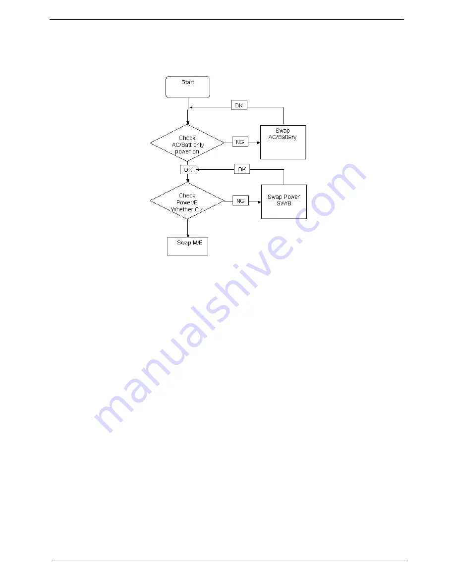
Power On Issue
If the system doesn’t power on, perform the following actions one at a time to correct the problem. Do not
replace a non-defective FRUs:
Computer Shuts down Intermittently
If the system powers off at intervals, perform the following actions one at a time to correct the problem.
1.
Check the power cable is properly connected to the computer and the electrical outlet.
2.
Remove any extension cables between the computer and the outlet.
3.
Remove any surge protectors between the computer and the electrical outlet. Plug the computer directly
into a known good electrical outlet.
4.
Disconnect the power and open the casing to check the Thermal Unit (see “Thermal Unit Failure” on page
136) and fan airways are free of obstructions.
5.
Remove all external and non-essential hardware connected to the computer that are not necessary to
boot the computer to the failure point.
6.
Remove any recently installed software.
7.
If the Issue is still not resolved, see “Online Support Information” on page 215.
Содержание Aspire 5332 Series
Страница 6: ...VI...
Страница 10: ...X Table of Contents...
Страница 13: ...Chapter 1 3 Humidity non condensing Operating 20 to 80 Non operating 20 to 80...
Страница 34: ...24 Chapter 1...
Страница 56: ...46 Chapter 2...
Страница 78: ...68 Chapter 3 4 Disconnect the following four cables from the Mainboard labeled A B C and D A B C D...
Страница 92: ...82 Chapter 3 4 Lift the CPU Fan clear of the Mainboard as shown...
Страница 98: ...88 Chapter 3 5 Lift the LCD Panel clear of the module...
Страница 106: ...96 Chapter 3 9 The Antennas and cables appear as shown when correctly installed...
Страница 111: ...Chapter 3 101 2 Replace the four 4 screws and screw caps provided...
Страница 116: ...106 Chapter 3 5 Replace the FFC and press down as indicated to adhere it to the Upper Cover...
Страница 121: ...Chapter 3 111 4 Replace the three 3 screw caps as shown 5 Connect the following cables to the Mainboard A B C D...
Страница 127: ...Chapter 3 117 17 Replace the two 2 screws securing the LCD Module to the Lower Cover...
Страница 162: ...152 Chapter 5...
Страница 175: ...Chapter 6 165...
Страница 226: ...216 Appendix C...
Страница 230: ...220...


