


38
Chapter 2
DOS Flash Utility
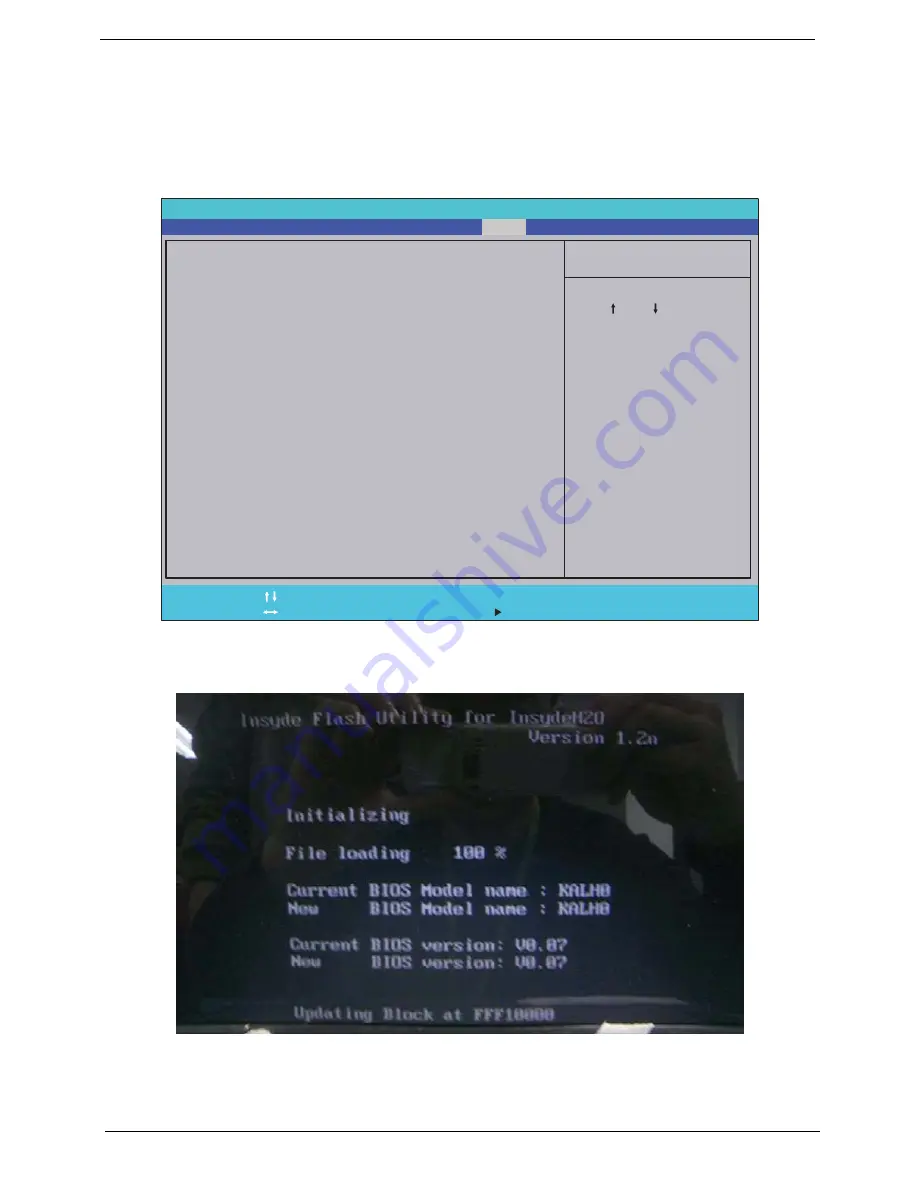
Perform the following steps to use the DOS Flash Utility:
1.
Press F2 during boot to enter the Setup Menu.
2.
Select
Boot Menu
to modify the boot priority order, for example, if using USB HDD to Update BIOS, move
USB HDD to position 1.
3.
Execute the
FLASH.BAT
batch file to update BIOS.
The flash process begins as shown.
I t e m S p e c i f i c H e l p
U s e < > o r < > t o s e l e c t
a d e v i c e , t h e n p r e s s
< F 5 > t o m o v e i t d o w n t h e
l i s t , o r < F 6 > t o m o v e
i t u p t h e l i s t . P r e s s
< E s c > t o e s c a p e t h e m e n u
F 1
E S C
H e l p
E x i t
S e l e c t I t e m
S e l e c t M e n u
C h a n g e Va l u e s
S e l e c t
S u b M e n u
E n t e r
F 9
F 1 0
S e t u p D e f a u l t
S a v e a n d E x i t
B o o t p r i o r i t y o r d e r :
1 . I D E 0 : W D C W D 5 0 0 0 B E V T - 2 2 Z A T 0
2 . I D E 2 :
3 . I D E 1 : M A T S H I T A D V D - R A M U J 8 8 0 A S
3 . U S B F D D :
4 . N e t w o r k B o o t : A t h e r o s B o o t A g e n t
5 . U S B H D D :
6 . U S B C D R O M :
B o o t p r i o r i t y o r d e r :
1 . I D E 0 : W D C W D 5 0 0 0 B E V T - 2 2 Z A T 0
2 . I D E 2 :
3 . I D E 1 : M A T S H I T A D V D - R A M U J 8 8 0 A S
3 . U S B F D D :
4 . N e t w o r k B o o t : A t h e r o s B o o t A g e n t
5 . U S B H D D :
6 . U S B C D R O M :
F 5 / F 6
I n s y d e H 2 0 S e t u p U t i l i t y R e v . 3 . 5
Information
Advanced
Main
Boot
Exit
Security
Power
Содержание Aspire 5332 Series
Страница 6: ...VI...
Страница 10: ...X Table of Contents...
Страница 13: ...Chapter 1 3 Humidity non condensing Operating 20 to 80 Non operating 20 to 80...
Страница 34: ...24 Chapter 1...
Страница 56: ...46 Chapter 2...
Страница 78: ...68 Chapter 3 4 Disconnect the following four cables from the Mainboard labeled A B C and D A B C D...
Страница 92: ...82 Chapter 3 4 Lift the CPU Fan clear of the Mainboard as shown...
Страница 98: ...88 Chapter 3 5 Lift the LCD Panel clear of the module...
Страница 106: ...96 Chapter 3 9 The Antennas and cables appear as shown when correctly installed...
Страница 111: ...Chapter 3 101 2 Replace the four 4 screws and screw caps provided...
Страница 116: ...106 Chapter 3 5 Replace the FFC and press down as indicated to adhere it to the Upper Cover...
Страница 121: ...Chapter 3 111 4 Replace the three 3 screw caps as shown 5 Connect the following cables to the Mainboard A B C D...
Страница 127: ...Chapter 3 117 17 Replace the two 2 screws securing the LCD Module to the Lower Cover...
Страница 162: ...152 Chapter 5...
Страница 175: ...Chapter 6 165...
Страница 226: ...216 Appendix C...
Страница 230: ...220...


