


Chapter 3
87
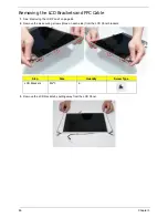
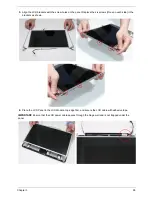
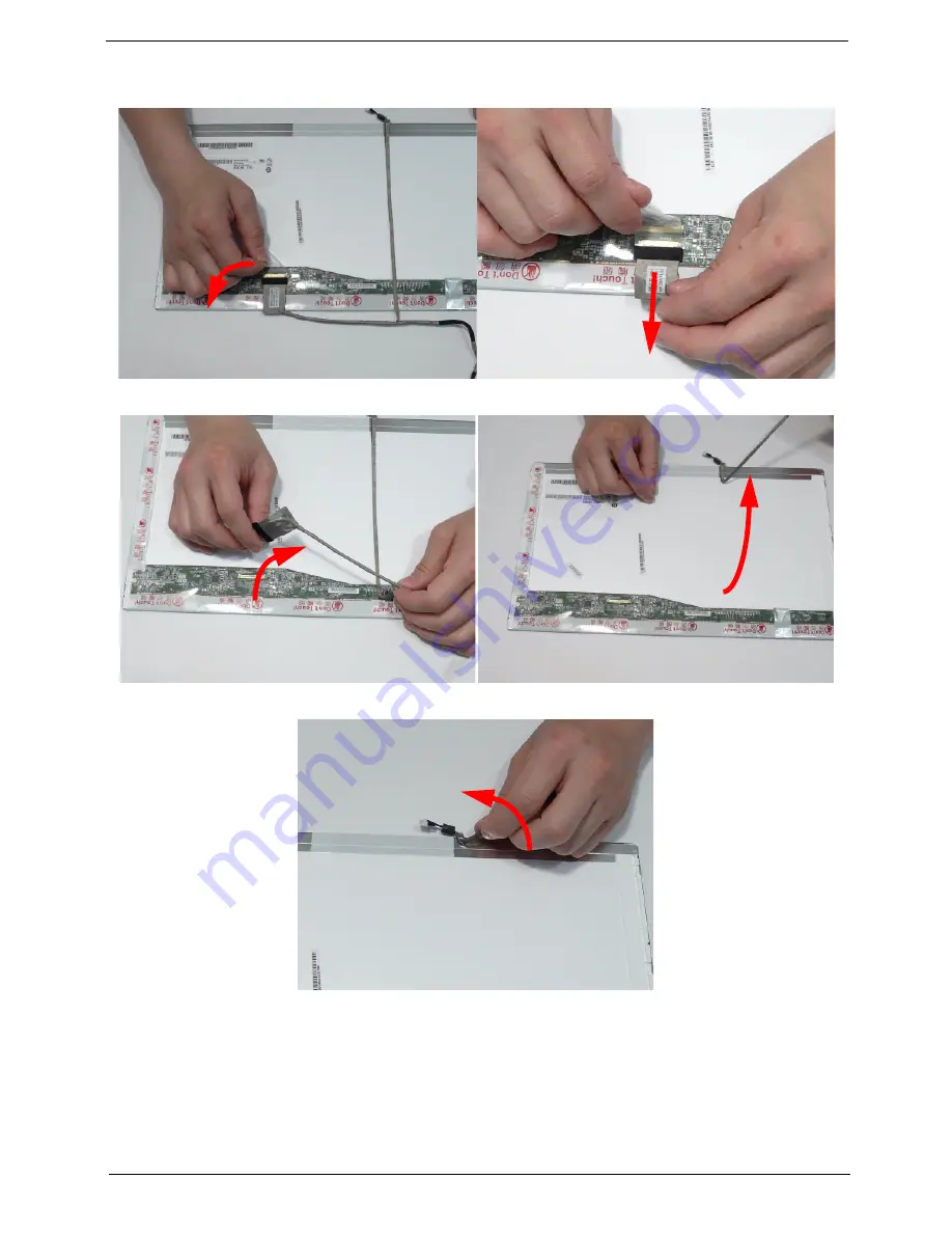
4.
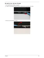
Turn the LCD panel over to expose the rear. Lift the adhesive protector and disconnect the cable from the LCD
Panel.
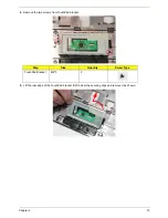
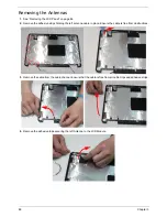
5.
Lift the cable as shown to disengage the adhesive strip securing it in place.
6.
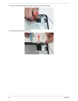
Lift the FPC cable to disengage the remaining adhesive and remove the cable from the panel.
Содержание AS7315-302G25Mn
Страница 6: ...VI ...
Страница 10: ...X Table of Contents ...
Страница 13: ...Chapter 1 3 System Block Diagram ...
Страница 30: ...20 Chapter 1 ...
Страница 52: ...42 Chapter 2 ...
Страница 74: ...64 Chapter 3 4 Disconnect the following four cables from the Mainboard A B C D ...
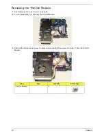
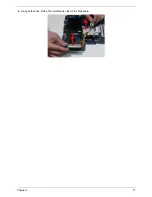
Страница 87: ...Chapter 3 77 4 Using both hands lift the Thermal Module clear of the Mainboard ...
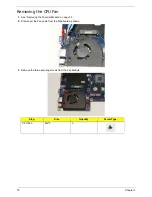
Страница 89: ...Chapter 3 79 4 Lift the CPU Fan clear of the Mainboard as shown ...
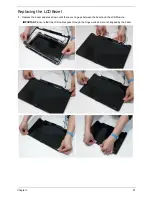
Страница 95: ...Chapter 3 85 5 Lift the LCD Panel clear of the module ...
Страница 103: ...Chapter 3 93 9 The Antennas and cables appear as shown when correctly installed ...
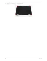
Страница 108: ...98 Chapter 3 2 Replace the four screws and screw caps provided ...
Страница 113: ...Chapter 3 103 5 Replace the FFC and press down as indicated to secure it to the Upper Cover ...
Страница 117: ...Chapter 3 107 2 Press down around the edges to secure it in place 3 Replace the nine screws in the Upper Cover as shown ...
Страница 118: ...108 Chapter 3 4 Replace the three screw caps as shown 5 Connect the following cables to the Mainboard A B C D ...
Страница 124: ...114 Chapter 3 17 Replace the two screws securing the LCD Module to the Lower Cover ...
Страница 132: ...122 Chapter 3 ...
Страница 163: ...Chapter 6 153 Base Assembly No Description Acer P N 1 CPU Fan 2 Thermal Module 3 4 5 Mainboard 1 2 3 4 5 ...
Страница 164: ...154 Chapter 6 Rear Assembly No Description Acer P N 1 HDD Cover 2 3 RAM Cover 4 5 1 2 3 4 5 ...
Страница 174: ...Appendix A 164 Model Definition and Configuration Appendix A ...
Страница 196: ...186 Appendix C ...
Страница 200: ...190 ...