


Chapter 1
11
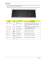
Windows Keys
The keyboard has two keys that perform Windows-specific functions.
Key
Description
Windows key
Pressed alone, this key has the same effect as clicking on the Windows Start button;
it launches the Start menu. It can also be used with other keys to provide a variety of
functions:
<
>
:
Open or close the Start menu
<
>
+ <D>:
Display the desktop
<
>
+ <E>:
Open Windows Explore
<
>
+ <F>:
Search for a file or folder
<
>
+ <G>:
Cycle through Sidebar gadgets
<
>
+ <L>:
Lock your computer (if you are connected to a network domain), or
switch users (if you're not connected to a network domain)
<
>
+ <M>:
Minimizes all windows
<
>
+ <R>:
Open the Run dialog box
<
>
+ <T>:
Cycle through programs on the taskbar
<
>
+ <U>:
Open Ease of Access Center
<
>
+ <X>:
Open Windows Mobility Center
<
>
+ <BREAK>:
Display the System Properties dialog box
<
>
+ <SHIFT+M>:
Restore minimized windows to the desktop
<
>
+ <TAB>:
Cycle through programs on the taskbar by using Windows Flip 3-D
<
>
+ <SPACEBAR>:
Bring all gadgets to the front and select Windows Sidebar
<CTRL> +
<
>
+ <F>:
Search for computers (if you are on a network)
<CTRL> +
<
>
+ <TAB>:
Use the arrow keys to cycle through programs on the
taskbar by using Windows Flip 3-D
Note:
Depending on your edition of Windows 7, some shortcuts may not function as
described.
Application
key
This key has the same effect as clicking the right mouse button; it opens the
application's context menu.
Содержание AS7315-302G25Mn
Страница 6: ...VI ...
Страница 10: ...X Table of Contents ...
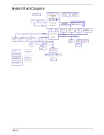
Страница 13: ...Chapter 1 3 System Block Diagram ...
Страница 30: ...20 Chapter 1 ...
Страница 52: ...42 Chapter 2 ...
Страница 74: ...64 Chapter 3 4 Disconnect the following four cables from the Mainboard A B C D ...
Страница 87: ...Chapter 3 77 4 Using both hands lift the Thermal Module clear of the Mainboard ...
Страница 89: ...Chapter 3 79 4 Lift the CPU Fan clear of the Mainboard as shown ...
Страница 95: ...Chapter 3 85 5 Lift the LCD Panel clear of the module ...
Страница 103: ...Chapter 3 93 9 The Antennas and cables appear as shown when correctly installed ...
Страница 108: ...98 Chapter 3 2 Replace the four screws and screw caps provided ...
Страница 113: ...Chapter 3 103 5 Replace the FFC and press down as indicated to secure it to the Upper Cover ...
Страница 117: ...Chapter 3 107 2 Press down around the edges to secure it in place 3 Replace the nine screws in the Upper Cover as shown ...
Страница 118: ...108 Chapter 3 4 Replace the three screw caps as shown 5 Connect the following cables to the Mainboard A B C D ...
Страница 124: ...114 Chapter 3 17 Replace the two screws securing the LCD Module to the Lower Cover ...
Страница 132: ...122 Chapter 3 ...
Страница 163: ...Chapter 6 153 Base Assembly No Description Acer P N 1 CPU Fan 2 Thermal Module 3 4 5 Mainboard 1 2 3 4 5 ...
Страница 164: ...154 Chapter 6 Rear Assembly No Description Acer P N 1 HDD Cover 2 3 RAM Cover 4 5 1 2 3 4 5 ...
Страница 174: ...Appendix A 164 Model Definition and Configuration Appendix A ...
Страница 196: ...186 Appendix C ...
Страница 200: ...190 ...