


187
A
AFLASH Utility
33
Antennas
Removing
88
Replacing
91
B
Battery
Replacing
121
Battery Pack
Removing
46
BIOS
ROM type
14
vendor
14
Version
14
BIOS Utility
21–33
Advanced
24
Boot
31
Exit
32
Navigating
21
Onboard Device Configuration
27
Power
29
Save and Exit
32
Security
26
System Security
32
Board Layout
Top View
145
brightness
hotkeys
12
C
Camera Module
Removing
83
Replacing
96
caps lock
on indicator
5, 8
Common Problems
124
computer
on indicator
5, 8
CPU
Removing
80
Replacing
99
CPU Fan
Removing
78
Replacing
100
D
DIMM Modules
Removing
51
Replacing
118
Display
3
display
hotkeys
12
E
EasyTouch Failure
134
External Module Disassembly
Flowchart
45
F
Features
1
Flash Utility
33
FPC Cable
Removing
86
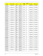
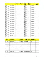
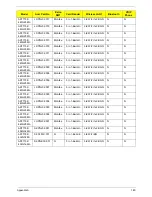
FRU (Field Replaceable Unit) List
151
H
Hard Disk Drive
Removing
54
Replacing
116
HDTV Switch Failure
135
Hibernation mode
hotkey
12
Hot Keys
10
I
Indicators
8
Intermittent Problems
136
Internal Microphone Failure
129
Internal Speaker Failure
128
J
Jumper and Connector Locations
145
K
Keyboard
Index
Содержание AS7315-302G25Mn
Страница 6: ...VI ...
Страница 10: ...X Table of Contents ...
Страница 13: ...Chapter 1 3 System Block Diagram ...
Страница 30: ...20 Chapter 1 ...
Страница 52: ...42 Chapter 2 ...
Страница 74: ...64 Chapter 3 4 Disconnect the following four cables from the Mainboard A B C D ...
Страница 87: ...Chapter 3 77 4 Using both hands lift the Thermal Module clear of the Mainboard ...
Страница 89: ...Chapter 3 79 4 Lift the CPU Fan clear of the Mainboard as shown ...
Страница 95: ...Chapter 3 85 5 Lift the LCD Panel clear of the module ...
Страница 103: ...Chapter 3 93 9 The Antennas and cables appear as shown when correctly installed ...
Страница 108: ...98 Chapter 3 2 Replace the four screws and screw caps provided ...
Страница 113: ...Chapter 3 103 5 Replace the FFC and press down as indicated to secure it to the Upper Cover ...
Страница 117: ...Chapter 3 107 2 Press down around the edges to secure it in place 3 Replace the nine screws in the Upper Cover as shown ...
Страница 118: ...108 Chapter 3 4 Replace the three screw caps as shown 5 Connect the following cables to the Mainboard A B C D ...
Страница 124: ...114 Chapter 3 17 Replace the two screws securing the LCD Module to the Lower Cover ...
Страница 132: ...122 Chapter 3 ...
Страница 163: ...Chapter 6 153 Base Assembly No Description Acer P N 1 CPU Fan 2 Thermal Module 3 4 5 Mainboard 1 2 3 4 5 ...
Страница 164: ...154 Chapter 6 Rear Assembly No Description Acer P N 1 HDD Cover 2 3 RAM Cover 4 5 1 2 3 4 5 ...
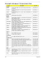
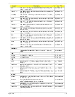
Страница 174: ...Appendix A 164 Model Definition and Configuration Appendix A ...
Страница 196: ...186 Appendix C ...
Страница 200: ...190 ...