


30
Chapter 2
Changing a Password
1.
Use the
and
keys to highlight the Set Supervisor Password parameter and press the Enter key. The
Set Password box appears.
2.
Type the current password in the Enter Current Password field and press Enter.
3.
Type a password in the Enter New Password field. Retype the password in the Confirm New Password
field.
4.
Press Enter. After setting the password, the computer sets the User Password parameter to “Set”.
5.
If desired, you can enable the Password on boot parameter.
6.
When you are done, press F10 to save the changes and exit the BIOS Setup Utility.
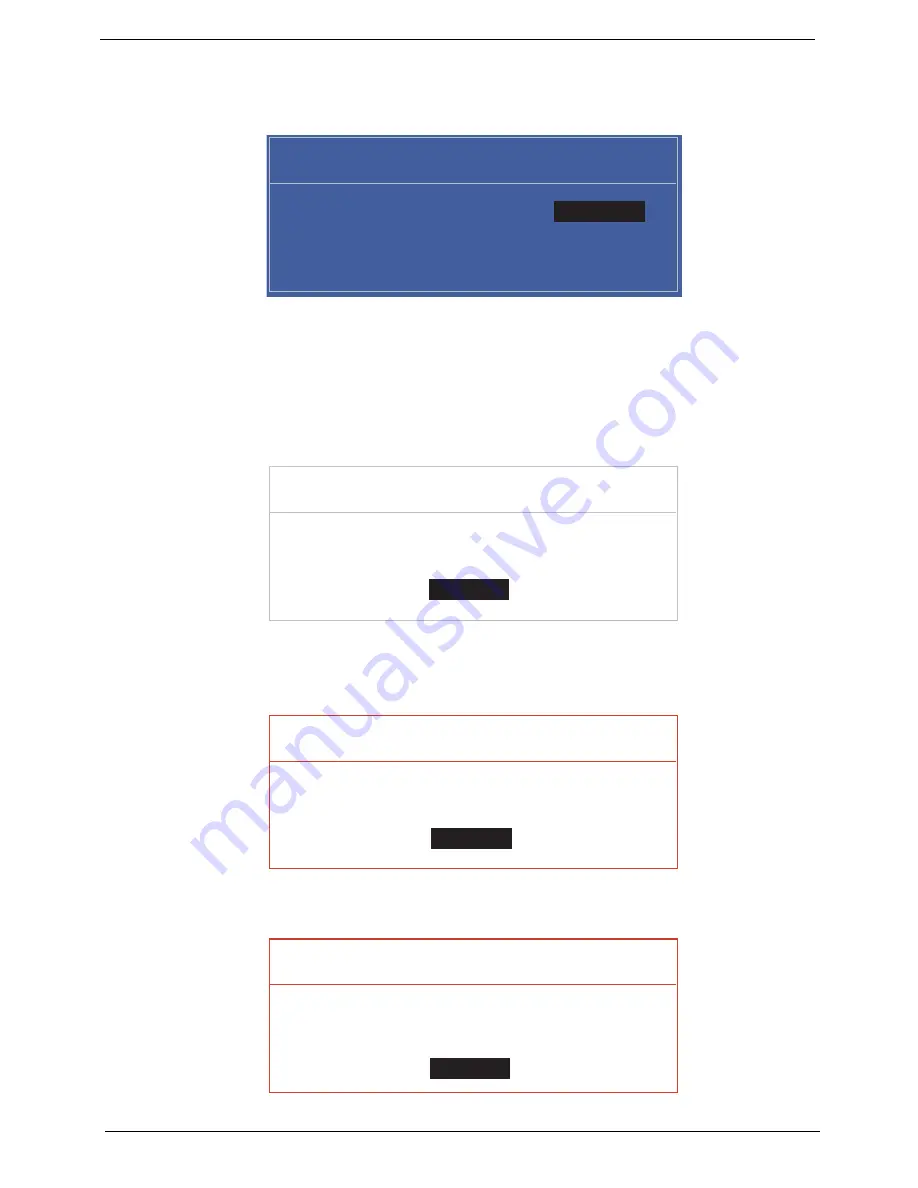
If the verification is OK, the screen will display as following.
The password setting is complete after the user presses Enter.
If the current password entered does not match the actual current password, the screen will show you the
Setup Warning.
If the new password and confirm new password strings do not match, the screen displays the following
message.
Set Supervisor Passwor
d
Enter Current Passwor
d
v
v
Enter New Password v
v
Confirm New Password
v
v
Setup Notice
Changes have been saved.
vContinuev
v
Continue
v
Setup Warning
Invalid Password.
vContinuev
v
Continue
v
Setup Warning
Passwords do not match.
Re-enter password.
vContinuev
v
Continue
v
Содержание AO752
Страница 6: ...VI ...
Страница 10: ...X Table of Contents ...
Страница 34: ...24 Chapter 1 ...
Страница 50: ...40 Chapter 2 ...
Страница 59: ...Chapter 3 49 9 Detach the HDD board ...
Страница 61: ...Chapter 3 51 5 Pull the memory module out 6 Repeat steps 4 and 5 for the second memory module ...
Страница 73: ...Chapter 3 63 7 Unlock the touch pad FCC and pull the cable away ...
Страница 77: ...Chapter 3 67 4 Lift off the LCD Board 5 Unlock and remove the LED board FCC from the mainboard ...
Страница 87: ...Chapter 3 77 4 Pull the cables away from the two adhesive locations 5 Lift the modules away ...
Страница 91: ...Chapter 3 81 5 Roll the bezel up and away from the hinges ...
Страница 94: ...84 Chapter 3 4 Lift the LCD panel out lifting the bottom of the panel first ...
Страница 99: ...Chapter 3 89 7 Lift up the right antenna 8 Pull the right antenna cable away from the LCD module ...
Страница 106: ...96 Chapter 3 3 Apply adhesive and stick the microphone down ...
Страница 113: ...Chapter 3 103 Replacing the RTC Battery 1 Place the RTC battery into the holding clips on the main board ...
Страница 117: ...Chapter 3 107 3 Connect the speaker connector ...
Страница 135: ...Chapter 3 125 4 Tighten the four captive screws ...
Страница 137: ...Chapter 3 127 4 Place the HDD cover in from one corner 5 Tighten the two captive screws ...
Страница 138: ...128 Chapter 3 Replacing the Battery 1 Slide the battery into position 2 Close the locking latch ...
Страница 139: ...Chapter 3 129 Replace the Dummy Card Push the dummy card into the slot until it clicks into place ...
Страница 140: ...130 Chapter 3 ...
Страница 240: ...230 Appendix A ...
Страница 250: ...240 Appendix B ...
Страница 252: ...242 ...
Страница 255: ...245 ...
Страница 256: ...246 ...


