


Chapter 1
19
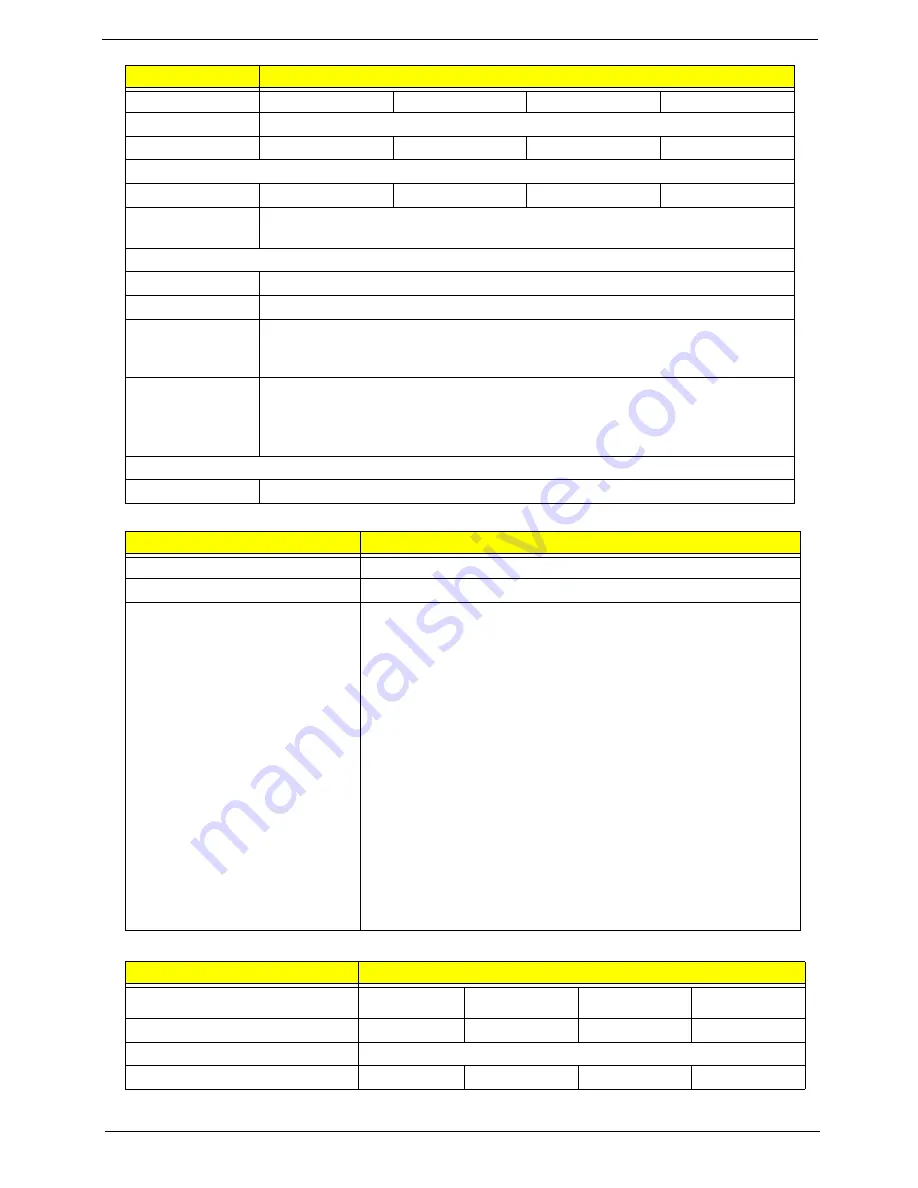
BIOS
LCD 11.6”
Capacity (GB)
160
250
320
500
Bytes per sector
512
Data heads
2
4
3
4
Drive Format
Disks
1
2
2
2
Spindle speed
(RPM)
5400
Performance Specifications
Buffer size
8 MB
Interface
SATA
Internal transfer
rate (Mbits/sec,
max)
N/A
I/O data transfer
rate
(Mbytes/sec
max)
300
DC Power Requirements
Voltage
5V ±5%
Item
Specification
BIOS vendor
Insyde
BIOS Version
3.5
BIOS Features
•
Flash ROM 1MB
•
Support ISIPP
•
Support Acer UI
•
Support multi-boot
•
Suspend to RAM (S3) / Disk (S4)
•
Various hot-keys for system control
•
Support SMBUS 2.0, PCI2.3
•
ACPI 2.0 compliance with Intel Speed Step Support C1e, C2,
C3 and S3, S4,S5 for mobile CPU.
•
DMI utility for BIOS serial number configuration/asset tag
•
Support PXE
•
Support Y2K solution
•
Support Win Flash Wake on LAN from S3
•
Wake on LAN form S4 in AC mode
•
System information
Item
Specifications
Vendor/model name
AUO
B11.6XW02
CMO N116B6-
L02
LG LP116WH1-
TLA1
Samsung
LTN116AT01-A01
Screen Diagonal (mm)
11.6”
11.6”
11.6”
11.6”
Display Area (mm)
256.125 x 144 (11.6” diagonal)
Display resolution (pixels)
1366 x 768
1366 x 768
1366 x 768
1366 x 768
Item
Specifications
Содержание AO752
Страница 6: ...VI ...
Страница 10: ...X Table of Contents ...
Страница 34: ...24 Chapter 1 ...
Страница 50: ...40 Chapter 2 ...
Страница 59: ...Chapter 3 49 9 Detach the HDD board ...
Страница 61: ...Chapter 3 51 5 Pull the memory module out 6 Repeat steps 4 and 5 for the second memory module ...
Страница 73: ...Chapter 3 63 7 Unlock the touch pad FCC and pull the cable away ...
Страница 77: ...Chapter 3 67 4 Lift off the LCD Board 5 Unlock and remove the LED board FCC from the mainboard ...
Страница 87: ...Chapter 3 77 4 Pull the cables away from the two adhesive locations 5 Lift the modules away ...
Страница 91: ...Chapter 3 81 5 Roll the bezel up and away from the hinges ...
Страница 94: ...84 Chapter 3 4 Lift the LCD panel out lifting the bottom of the panel first ...
Страница 99: ...Chapter 3 89 7 Lift up the right antenna 8 Pull the right antenna cable away from the LCD module ...
Страница 106: ...96 Chapter 3 3 Apply adhesive and stick the microphone down ...
Страница 113: ...Chapter 3 103 Replacing the RTC Battery 1 Place the RTC battery into the holding clips on the main board ...
Страница 117: ...Chapter 3 107 3 Connect the speaker connector ...
Страница 135: ...Chapter 3 125 4 Tighten the four captive screws ...
Страница 137: ...Chapter 3 127 4 Place the HDD cover in from one corner 5 Tighten the two captive screws ...
Страница 138: ...128 Chapter 3 Replacing the Battery 1 Slide the battery into position 2 Close the locking latch ...
Страница 139: ...Chapter 3 129 Replace the Dummy Card Push the dummy card into the slot until it clicks into place ...
Страница 140: ...130 Chapter 3 ...
Страница 240: ...230 Appendix A ...
Страница 250: ...240 Appendix B ...
Страница 252: ...242 ...
Страница 255: ...245 ...
Страница 256: ...246 ...


