


12
Chapter 1
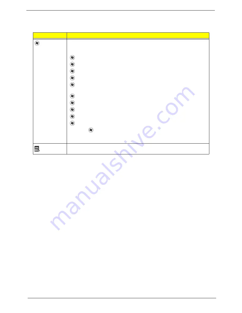
Windows Keys
The keyboard has two keys that perform Windows-specific functions.
Key
Description
Windows key
Pressed alone, this key has the same effect as clicking on the Windows Start button;
it launches the Start menu. It can also be used with other keys to provide a variety of
functions:
<
>
: Open or close the Start menu
<
>
+ <D>: Display the desktop
<
>
+ <E>: Open Windows Explore
<
>
+ <F>: Search for a file or folder
<
>
+ <L>: Lock your computer (if you are connected to a network domain), or
switch users (if you're not connected to a network domain)
<
>
+ <M>: Minimizes all windows
<
>
+ <R>: Open the Run dialog box
<
>
+ <U>: Open Ease of Access Center
<
>
+ <BREAK>: Display the System Properties dialog box
<
>
+ <TAB>: Cycle through programs on the task bar
<CTRL> +
<
>
+ <F>: Search for computers (if you are on a network)
Note: Depending on your edition of Windows XP, some shortcuts may not function
as described.
Application
key
This key has the same effect as clicking the right mouse button; it opens the
application's context menu.
Содержание AO752
Страница 6: ...VI ...
Страница 10: ...X Table of Contents ...
Страница 34: ...24 Chapter 1 ...
Страница 50: ...40 Chapter 2 ...
Страница 59: ...Chapter 3 49 9 Detach the HDD board ...
Страница 61: ...Chapter 3 51 5 Pull the memory module out 6 Repeat steps 4 and 5 for the second memory module ...
Страница 73: ...Chapter 3 63 7 Unlock the touch pad FCC and pull the cable away ...
Страница 77: ...Chapter 3 67 4 Lift off the LCD Board 5 Unlock and remove the LED board FCC from the mainboard ...
Страница 87: ...Chapter 3 77 4 Pull the cables away from the two adhesive locations 5 Lift the modules away ...
Страница 91: ...Chapter 3 81 5 Roll the bezel up and away from the hinges ...
Страница 94: ...84 Chapter 3 4 Lift the LCD panel out lifting the bottom of the panel first ...
Страница 99: ...Chapter 3 89 7 Lift up the right antenna 8 Pull the right antenna cable away from the LCD module ...
Страница 106: ...96 Chapter 3 3 Apply adhesive and stick the microphone down ...
Страница 113: ...Chapter 3 103 Replacing the RTC Battery 1 Place the RTC battery into the holding clips on the main board ...
Страница 117: ...Chapter 3 107 3 Connect the speaker connector ...
Страница 135: ...Chapter 3 125 4 Tighten the four captive screws ...
Страница 137: ...Chapter 3 127 4 Place the HDD cover in from one corner 5 Tighten the two captive screws ...
Страница 138: ...128 Chapter 3 Replacing the Battery 1 Slide the battery into position 2 Close the locking latch ...
Страница 139: ...Chapter 3 129 Replace the Dummy Card Push the dummy card into the slot until it clicks into place ...
Страница 140: ...130 Chapter 3 ...
Страница 240: ...230 Appendix A ...
Страница 250: ...240 Appendix B ...
Страница 252: ...242 ...
Страница 255: ...245 ...
Страница 256: ...246 ...


