background image

35

4

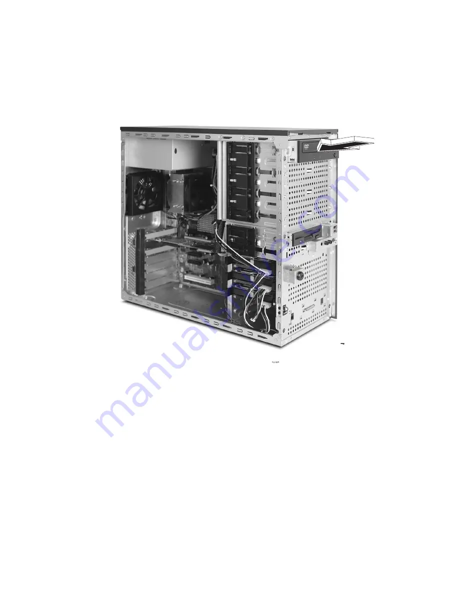
Transfer the left side tool-less locking rail (looking from the front) 
from the old drive to the new drive module.

5

Insert the new CD-ROM drive into the drive bay until it locks into 
place with an audible "click."

6

Connect the power and IDE cables to the new drive.

7

Observe the post-installation instructions described on page 30. 

Содержание Altos G310 MK2 Series

Страница 1: ...Acer Altos G310 Mk2 series ...

Страница 2: ...puter All correspondense concerning your unit should include the serial number model number and purchase information No part of this publication may be reproduced stored in a retrieval system or transmitted in any form or by any means electronically mechanically by photocopy recording or otherwise without the prior written permission of Acer Incorporated Model Number ______________________________...

Страница 3: ...adio frequency energy and if not installed and used in accordance with the instructions may cause harmful interference to radio communications However there is no guarantee that interference will not occur in a particular installation If this device does cause harmful interference to radio or television reception which can be determined by turning the device off and on the user is encouraged to tr...

Страница 4: ... is granted by the Federal Communications Commission to operate this server Use conditions This part complies with Part 15 of the FCC Rules Operation is subject to the following two conditions 1 this device may not cause harmful interference and 2 this device must accept any interference received including interference that may cause undesired operation Notice Canadian users This Class A Class B d...

Страница 5: ... from the type of power source indicated on the label If you are unsure of the type of power source available consult your dealer or local power company before use 7 Do not allow anything to rest on the power cord Carefully route the power cord and any cables away from foot traffic 8 If an extension cord is used with this product make sure that the total ampere rating of the equipment plugged into...

Страница 6: ...e indicating a need for service 12 Replace the battery with the same type as the product s battery we recommend Use of another battery may present a risk of fire or explosion Refer battery replacement to a qualified service technician 13 Warning Batteries may explode if not handled properly Do not disassemble or dispose of them in fire Keep them away from children and dispose of used batteries pro...

Страница 7: ...n summary 7 2 System tour 9 System board 11 Mainboard layout 11 Jumper settings and CMOS clear 13 External and internal structure 14 Front bezel 14 Front panel 16 Rear panel 18 Internal components 20 3 Getting Started 21 Setting up the system 23 Preinstallation requirements 23 Selecting a site 23 Checking the package contents 23 System startup 24 Turning on the system 24 Turning off the system 25 ...

Страница 8: ...ding the system memory 41 Memory configuration 41 To remove a DIMM 43 To install a DIMM 44 Reconfiguring the system memory 44 Installing an expansion card 45 To install an expansion card 45 Installing and removing a hard disk 47 To remove a hard disk 47 To install a hard disk 47 5 BIOS setup 49 BIOS setup 51 Entering BIOS setup 52 Main 54 Advanced 55 PCI Configuration 56 Boot Configuration 57 Peri...

Страница 9: ...t rotate properly 87 Floppy disk drive activity light does not light 88 CD ROM drive or DVD ROM drive activity light does not light 88 Cannot connect to a server 88 Problems with the network 89 The server hangs when the drivers are loaded 89 Diagnostics pass but the connection fails 89 The controller stopped working when an add in adaptor was installed 89 The add in adaptor stopped working without...

Страница 10: ...figuration 107 Configuration menu screen 108 Logical drive configuration screen 109 New configuration and view add configuration 109 Initializing logical drives 111 Logical drive submenu 112 Rebuilding failed disks 112 Inserting a previously removed drive from a RAID 1 array 113 Checking data consistency 113 Troubleshooting 115 Problems and suggested solutions 115 Appendix B Configuring SCSI SCSI ...

Страница 11: ...Create RAID1 volume 121 Assign hot spare disk 122 Initialize RAID volume 122 Save and exit MegaRAID configuration utility 122 ...

Страница 12: ...Contents ...

Страница 13: ...1 System information ...

Страница 14: ...The Acer Altos G310 Mk2 server is an entry level single processor general purpose system The system offers a new standard for flexible productivity ideal for small business or workgroup applications ...

Страница 15: ...al memory channel support Maximum upgrade 4 GB Two way interleaving support Warning Functionality issues may be encountered if mixed memory types are installed on the same server board DIMM modules of identical type banking and stacking technology and vendor should be installed in the Altos G310 Mk2 Caution When using multiple memory modules it is recommended that you AVOID using modules from diff...

Страница 16: ...e Integrated PCI Express x8 graphics controller Networking Integrated dual port Ethernet Marvell 88E8050 Gigabit Ethernet LAN controller Intel 82551QM 10 100 Ethernet LAN controller I O ports Front Two USB 2 0 ports Rear Four USB 2 0 ports Two PS 2 ports keyboard mouse Two LAN ports RJ 45 One parallel port One serial port One VGA port Serial ATA ports Four Serial ATA ports supporting RAID 0 or RAI...

Страница 17: ...pler and faster The Altos G310 Mk2 is no exception to this rule The following features and options are provided Cost efficient operation in a value oriented package Tool less design Front accessible USB ports Integrated graphics Acer EasyBUILDTM optional for efficient system setup and installation Acer Server Manager ASM suite of comprehensive management tools optional ...

Страница 18: ...1 System information 6 ...

Страница 19: ...8 Graphics Controller Integrated dual port Ethernet Marvell 88E8050 Gigabit Ethernet LAN controller Intel 82551QM 10 100 Ethernet LAN controller Three PCI 32 bit 33 MHz slots Two PCI Express x4 slot with x1 throughput One PCI Express x8 slot Media storage One 3 5 inch 1 44 MB floppy drive One 5 25 inch high speed CD ROM drive Additional media storage capacity Support for three 3 5 inch S ATA or SC...

Страница 20: ...1 System information 8 Operating Systems supported Microsoft Windows Server 2003 Red Hat Enterprise Linux 3 0 Novell Netware 6 5 ...

Страница 21: ...2 System tour ...

Страница 22: ...This chapter provides locations of various components and ports and instructions on how to set up the system Procedures on how to connect peripherals are also explained ...

Страница 23: ...r fan connector C PCI Express x4 w x1 throughout slot 2 D PCI Express x4 w x1 throughout slot 1 E Intel 82551QM LAN controller F PCI 32 bit 33 MHz slot 2 G PCI 32 bit 33 MHz slot 1 H Marvell 88E8050 PCI Express Gigabit Ethernet Controller I PCI Express x8 slot 1 J Back Panel I O K Two x 4 power connector A B C D E F G H I J L K M N O P Q R S T U V W X Y Z AA BB CC DD EE FF GG HH II ...

Страница 24: ...B DIMM 1 Black Socket U I O controller V Floppy disk drive connector W Two x12 Power connector X Parallel ATA IDE connector Y CMOS battery Z Chassis intrusion connector AA BIOS configuration jumper BB Clear CMOS jumper CC Front fan connector DD Serial ATA connectors EE Front panel USB connectors FF Serial B connector GG SCSI status LED connector HH Front panel connector II Intel 82801FR ICH6R I O ...

Страница 25: ...e maintenance menu is displayed Recovery None The BIOS attempts to recover the BIOS configuration A recovery floppy disk is required Function Mode Jumper Setting Configuration Normal 1 2 The BIOS uses current configuration information Clear CMOS 2 3 During POST the CMOS configuration is reset to default values No Jumper None Normal operation BIOS uses current configuration information OM16682 3 1 ...

Страница 26: ...l and internal structure Front bezel Note One pair of system keys are provided attached to the rear panel of the system No Description 1 CD ROM drive 2 CD ROM headphone port 3 CD ROM volume control 4 CD ROM activity indicator ...

Страница 27: ...DD floppy disk drive 7 FDD activity indicator 8 Security keylock 9 HDD activity indicator 10 System power indicator 11 System power button 12 USB 2 0 ports two 13 5 25 inch device bays 14 CD ROM stop eject button No Description ...

Страница 28: ...our 16 Front panel No Description 1 CD ROM drive 2 CD ROM headphone port 3 CD ROM volume control 4 CD ROM activity indicator 5 FDD eject button 6 FDD floppy disk drive 7 FDD activity indicator 8 Security keylock ...

Страница 29: ...17 9 HDD activity indicator 10 System power indicator 11 System power button 12 USB 2 0 ports two 13 5 25 inch device bays 14 CD ROM stop eject button No Description ...

Страница 30: ...2 System tour 18 Rear panel No Icon Description 1 Main power supply unit 2 PS 2 mouse port 3 PS 2 keyboard port 4 Parallel printer port 5 Serial port 6 VGA port ...

Страница 31: ...19 7 USB 2 0 ports four 8 LAN ports 9 Side panel tool less screws bottom 10 System ventilation fan exhaust 11 Main power supply fan exhaust 12 Side panel tool less screws top No Icon Description ...

Страница 32: ...2 System tour 20 Internal components No Description 1 Power supply unit 2 System fan 3 Mainboard 4 PCI slots 5 HDD bays 6 3 5 device bays 7 5 25 device bays ...

Страница 33: ...3 Getting Started ...

Страница 34: ...This chapter gives information on setting up and starting to use your system ...

Страница 35: ...ration Well ventilated and away from sources of heat Secluded from electromagnetic fields produced by electrical devices such as air conditioners radio and TV transmitters etc Checking the package contents Check the following items from the package Acer Altos G310 Mk2 series system Acer Altos G310 Mk2 series accessory box System keys attached to the rear panel of the system If any of the above ite...

Страница 36: ...er that a series of power on self test POST messages appears The POST messages indicate if the system is running well or not Note If the system does not turn on or boot after pressing the power button go to the next section for the possible causes of the boot failure Aside from the POST messages you can determine if the system is in good condition by checking if the following occurred Power indica...

Страница 37: ...rnal power cable may be loosely connected Check the power cable connection from the power source to the power cable socket on the rear panel Make sure that the cable is properly connected to the power source and to the power cable socket No power comes from the grounded power outlet Have an electrician check your power outlet Loose or improperly connected internal power cables Check the internal c...

Страница 38: ...3 Getting Started 26 ...

Страница 39: ...4 Configuring the system ...

Страница 40: ...This chapter discusses the precautionary measures and installation procedures you need to know when upgrading the system ...

Страница 41: ...you install any server component we recommend that you read the following sections These sections contain important ESD precautions along with preinstallation and post installation instructions ESD precautions Electrostatic discharge ESD can damage the processors motherboard disk drives expansion boards or other components Always observe the following precautions before you install a server compon...

Страница 42: ...ent connector See the following sections for specific installation instructions on the component you want to install Warning Failure to properly turn off the server before you start installing components may cause serious damage Do not attempt the procedures described in the following sections unless you are a qualified service technician Post installation instructions Observe the following after ...

Страница 43: ... panels are removable to allow access to the system s internal components Refer to the following sections for instructions Before opening the server Before opening the server observe the following precautions 1 Turn off the system and all the peripherals connected to it 2 Unplug all cables from the power outlets 3 Place the system unit on a flat stable surface Note Because of the G310 Mk2 design s...

Страница 44: ...server by two non removable thumbscrews To remove the side panel 1 Locate the System Keys if necessary and unlock the system lock on the front panel 2 Loosen the thumbscrews located at the rear end of the left panel 1 3 Slide the left panel rearward 2 before detaching it from the chassis ...

Страница 45: ...u must remove the side panel first To remove the front bezel 1 With your finger pull the front panel release lever located at the bottom front inside the chassis 1 2 Gently pull the bottom of the front bezel away from the chassis 2 lift it to approximately 45 degrees then detach the top and move it away from the chassis ...

Страница 46: ...ays allow you to install additional drives such as another CD ROM drive or a tape drive To install a 5 25 inch storage device Note If you are installing a new drive in an empty drive bay skip steps 2 to 4 1 Observe the ESD precautions and pre installation procedures described on page 30 2 Disconnect the power and IDE cables from the old drive 3 Lift the plastic tab that secures the drive in the ba...

Страница 47: ...he front from the old drive to the new drive module 5 Insert the new CD ROM drive into the drive bay until it locks into place with an audible click 6 Connect the power and IDE cables to the new drive 7 Observe the post installation instructions described on page 30 ...

Страница 48: ...ching the processor or server board Keep part of your body in contact with the metal chassis to dissipate the static charge while handling the processor 2 Avoid moving around unnecessarily To install the Processor Caution Before installing or removing the processor make sure that AC power has been removed by unplugging the power cord from the computer the standby power LED should not be lit Failur...

Страница 49: ...ver Always replace the socket cover if the processor is removed from the socket 4 Remove the processor from the protective processor cover Hold the processor only at the edges being careful not to touch the bottom of the processor Do not discard the protective processor cover Always replace the processor cover if the processor is removed from the socket ...

Страница 50: ...index fingers oriented as shown below Make sure fingers align to the socket cutouts Align notches with the socket Lower the processor straight down without tilting or sliding the processor in the socket 6 Pressing down on the load plate close and engage the socket lever ...

Страница 51: ...n heat sink The Altos G310 Mk2 s server board has an integrated processor fan heat sink retention mechanism RM Connecting the processor fan heat sink cable Connect the processor fan heat sink cable to the 4 pin processor fan header ...

Страница 52: ...erver s cover 5 Unplug the processor fan cable from the server board 6 Loosen the four captive screws on the corners of the heat sink 7 Twist the heat sink slightly to break the seal between the heat sink and the processor 8 Lift the heat sink from the processor If it does not pull up easily twist the heat sink again Do not force the heat sink from the processor Doing so could damage the processor...

Страница 53: ... the main server board as shown below The two tables below summarize the characteristics of 1 way and 2 way memory interleave configurations Memory Channel A Memory Channel B Memory Interleave DIMM0 DIMM1 DIMM0 DIMM1 512 MB 1 way 1 GB 512 MB 512 MB 2 way 1 GB 1 GB 512 MB 512 MB 512 MB 512 MB 2 way 1 GB 1 GB 1 GB 1 GB DIMM 1 DIMM 0 Channel A DIMM 1 DIMM 0 Channel B ...

Страница 54: ...42 Warning Functionality issues may be encountered if mixed memory types are installed on the same server board DIMM modules of identical type banking and stacking technology and vendor should be installed in the Altos G310 Mk2 ...

Страница 55: ...ant data 1 Observe the precautions and pre installation procedures described in ESD precautions on page 29 2 Locate the DIMM socket on the mainboard 3 Press the holding clips on both sides of the socket outward to release the DIMM 1 4 Gently pull the DIMM upward to remove it from the socket 2 Note Place your forefingers on the top of the DIMM before pressing the holding clips to gently disengage t...

Страница 56: ...2 Note The DIMM socket is slotted to ensure proper installation If you insert a DIMM but it does not fit easily into the socket you may have inserted it incorrectly Reverse the orientation of the DIMM and insert it again 6 Observe the Post installation instructions on page 30 Reconfiguring the system memory The system automatically detects the amount of memory installed Run the BIOS setup to view ...

Страница 57: ...rds To install an expansion card Note The illustrations used in this section show the Altos G310 Mk2 server chassis 1 Observe the ESD precautions and pre installation procedures described in ESD precautions on page 29 2 Remove the side panel to access the mainboard See To remove the side panel on page 32 for more information 3 Locate an empty expansion slot on the mainboard 4 Remove the tool less ...

Страница 58: ...t on the mainboard 8 Insert the bracket with the card into the selected slot 3 Make sure that the card is properly seated 9 Secure the card with the tool less bracket card lock removed in step three above 4 10 Observe the Post installation instructions on page 30 ...

Страница 59: ... computer s hard disk 1 Remove the side and front panels see page 32 and page 33 2 Detach the cables from the exposed end of the HDD 1 and 2 3 Squeeze the two locking tabs that secure the drive to the chassis slot and gently remove the HDD from the system 3 To install a hard disk Observe the pre installation and ESD precautions on page 29 Follow these steps to replace your computer s hard disk 1 3...

Страница 60: ...nel see page 32 2 Attach the HDD rails to the sides of the drive housing as shown below 3 Insert the drive into an empty HDD slot slot 1 or slot 3 until it locks into place with an audible click 1 4 Attach the power and IDE cables to the HDD 2 and 3 ...

Страница 61: ...5 BIOS setup ...

Страница 62: ...This chapter gives information about the system BIOS and discusses how to configure the system by changing the settings of the BIOS parameters ...

Страница 63: ...n Setup messages the battery may be bad In this case the system cannot retain configuration values in CMOS Ask a qualified technician for assistance When redefining the communication ports to prevent any conflicts When making changes to the Power Management configuration When changing the password or making other changes to the security setup BIOS setup loads the configuration values in a battery ...

Страница 64: ... Power Boot Exit The parameters on the screens shown in this User s Guide display default system values These values may not be the same as those in your system Note the following reminders when moving around the setup screen Use the Left and Right arrow keys to move to the next page or to return to the previous screen Use the Up and Down arrow keys to select an item Use the and keys to select an ...

Страница 65: ...een is available Press F1 for General Help on using the BIOS setup Press F9 to set up defaults Press F10 to save changes and close the BIOS setup Press Esc to close the BIOS setup In the descriptive table following each of the screen illustrations settings in boldface are the default and suggested parameter settings ...

Страница 66: ...nology only if OS supports it Enabled Disabled Additional System Information Display the system information Memory Correction Memory correction selection Non ECC ECC System Time Configures the system time on a 24 hour clock Default is 00 00 00 HH MM SS BIOS SETUP UTILITY Main Advanced Security Power Boot Exit BIOS Version BA92510A 86B 0149 Processor Type Genuine Intel R CPU Hyper Threading Technol...

Страница 67: ...curity Power Boot Exit Setup Warning Setting items on this screen to incorrect values may cause the system to malfunction PCI Configuration Boot Configuration Peripheral Configuration Drive Configuration Floppy Configuration Event Log Configuration Video Configuration USB Configuration PCI Express Configuration Chipset Configuration Fan Control Configuration Hardware Monitoring Remote Access Confi...

Страница 68: ...lot1 IRQ Priority Auto PCI Slot2 IRQ Priority Auto PCI Slot3 IRQ Priority Auto Manual IRQ selection does not guarantee PCI slot device will be configured with choice because PnP ISA cards If present are assigned the available resources before PCI devices Select Screen Select Item Enter Select Sub Menu Tab Select Field F1 General Help F9 Setup Defaults F10 Save and Exit ESC Exit ...

Страница 69: ...xtended CPUID functions Enabled Disabled BIOS SETUP UTILITY Advanced Boot Configuration Plug Play O S No Numlock On Max CPUID Value Limit Disabled No lets the BIOS configure all the devices in the system Yes lets the operating system configure Plug and Play PnP devices not required for boot if your system has a Plug and Play operating system Select Screen Select Item Enter Select Sub Menu Tab Sele...

Страница 70: ...sabled Auto Parallel port Indicates the configuration of the parallel port Enabled Disabled Auto BIOS SETUP UTILITY Advanced Peripheral Configuration Serial Port A Auto Serial Port B Auto Parallel Port Auto Mode Bi directional Onboard Gb LAN Enabled Onboard 10 100 LAN Enabled ASF Support Enabled Select Screen Select Item Enter Select Sub Menu Tab Select Field F1 General Help F9 Setup Defaults F10 ...

Страница 71: ...oard 10 100 LAN Sets onboard 10 100 LAN Enabled Disabled ASF Support Sets ASF support Enabled Disabled BIOS SETUP UTILITY Advanced Drive Configuration ATA IDE Configuration Enhanced Intel R RAID Technology Disabled SATA AHCI Mode Disabled PCI IDE Bus Master Enabled Hard Disk Pre Delay Disabled SATA Port 0 WDC WD1200JD 22GBB0 SATA Port 2 Not Detected SATA Port 1 Not Detected SATA Port 3 Not Detecte...

Страница 72: ...enabled Disabled Legacy Enhanced Intel RAID Technology Sets RAID function Enabled Disabled SATA AHCI Mode Sets SATA AHCI Mode Enabled Disabled PCI IDE Bus Master Sets PCI IDE Bus master Enabled Disabled Hard Disk Pre Delay Selects the hard disk drive pre delay Disabled N seconds SATA Port N Displays the status of auto detection of IDE devices PATA Master Slave Displays the status of auto detection...

Страница 73: ...2 1 44 MB 31 2 2 88 MB 31 2 Floppy disk write protect Disables Enables floppy disk drive write protection Enabled Disabled BIOS SETUP UTILITY Advanced Floppy Configuration Diskette Controller Enabled Floppy A 1 44 MB 3 1 2 Diskette Write Protect Disabled Configures the integrated diskette controller Select Screen Select Item Enter Select Sub Menu Tab Select Field F1 General Help F9 Setup Defaults ...

Страница 74: ...s Enabled to allow logging of ECC events Enabled Disabled Mark Events As Read Press Enter to mark all DMI events in the event log as read BIOS SETUP UTILITY Advanced Event Log Configuration Event Log Space Available View Event Log Clear Event Log Event Logging Enabled ECC Event Logging Enabled Mark Events As Read Views the contents of the DMI event log Select Screen Select Item Enter Select Sub Me...

Страница 75: ...Memory space for use by the internal graphics device 128MB 256MB DVMT MODE Selects IGD OS Driver memory allocation method FIXED DVMT BOTH IGD DVMT FIXED MEMORY Selects IGD OS Driver memory size used 32MB 64MB 128MB Maximum BIOS SETUP UTILITY Advanced Video Configuration Primary Video Adapter Auto Frame Buffer Size 8MB IGD Aperture Size 256MB DVMT MODE DVMT IGD DVMT FIXED MEMORY 128MB Allows select...

Страница 76: ...2 0 Legacy Support Configures the USB 2 0 Legacy support to HiSpeed 480Mpbs or FullSpeed 12Mbps Full Speed Hi Speed BIOS SETUP UTILITY Advanced USB Configuration High Speed USB Enabled Legacy USB Support Enabled USB 2 0 Legacy Support Full Speed Disables this function when a USB 2 0 driver is not available Select Screen Select Item Enter Select Sub Menu Tab Select Field F1 General Help F9 Setup De...

Страница 77: ...ility algorithm Enabled Disabled Compliance Test Pattern Selects the test pattern for PCI Express Enabled Disabled BIOS SETUP UTILITY Advanced PCIE x16 Link Retrain Disable Link Stability Algorithm Enabled Compliance Test Pattern Disabled PEG Negotiated Width None Select Screen Select Item Enter Select Sub Menu Tab Select Field F1 General Help F9 Setup Defaults F10 Save and Exit ESC Exit ...

Страница 78: ... 32 64 96 128 160 192 224 248 BIOS SETUP UTILITY Advanced Chipset Configuration Setup Warning Setting items on this screen to incorrect values may cause the system to malfunction ISA Enable Bit Enabled PCI Latency Timer 32 Some older expansion devices require this to be enabled Select Screen Select Item Enter Select Sub Menu Tab Select Field F1 General Help F9 Setup Defaults F10 Save and Exit ESC ...

Страница 79: ...e fans will continue to run at a slow speed Off At low system temperatures the fans will turn off Slow Off BIOS SETUP UTILITY Advanced Fan Control Configuration Note The new settings will not take effect until the system is completely shut down CPU Fan Control Enabled Fan Control Enabled Lowest Fan Speed Slow Enables or disables CPU fan control Select Screen Select Item Enter Select Sub Menu Tab S...

Страница 80: ...e Temperature 71 C 159 F System Zone 1 Temperature 36 C 96 F System Zone 2 Temperature 44 C 111 F Processor Fan Speed 3419 RPM Vreg Fan Speed 0 RPM Front Fan Speed 0 RPM Rear Fan Speed 0 RPM 1 5Vin 1 493 V Vccp 1 317 V 3 3Vin 3 310 V 5Vin 5 105 V 12Vin 12 000V Select Screen Select Item Enter Select Sub Menu Tab Select Field F1 General Help F9 Setup Defaults F10 Save and Exit ESC Exit ...

Страница 81: ... remote access type Enabled Disabled BIOS SETUP UTILITY Advanced Configure Remote Access type and parameters Remote Access Disabled Select Remote Access type Select Screen Select Item Enter Select Sub Menu Tab Select Field F1 General Help F9 Setup Defaults F10 Save and Exit ESC Exit ...

Страница 82: ...d Install or change the password Chassis Intrusion Sets chassis intrusion function Enabled Disabled BIOS SETUP UTILITY Main Advanced Security Power Boot Exit Supervisor Password Not Installed User Password Not Installed Set Supervisor Password Set User Password Chassis Intrusion Disabled Install or Change the password Select Screen Select Item Enter Select Sub Menu Tab Select Field F1 General Help...

Страница 83: ...ast State restores the system to the same state it was in before power failed Stay Off Last State Power On Wake on PCI PME Determines the action taken when the system power is off and a PCI Power Management Enable wake up event occurs Stay Off Power On BIOS SETUP UTILITY Main Advanced Security Power Boot Exit ACPI After Power Failure Last State The options below are not related to ACPI and may be ...

Страница 84: ...kip certain tests while booting Enabled Disabled Scan User Flash Area Allows BIOS to scan the Flash ROM for user binaries Enabled Disabled BIOS SETUP UTILITY Main Advanced Security Power Boot Exit Silent Boot Enabled AddOn ROM Display Mode Enabled Intel R Rapid BIOS Boot Enabled Scan User Falsh Area Enabled PXE Boot to LAN Disabled USB Boot Enabled Boot Device Priority Hard Disk Drives Removable D...

Страница 85: ...ll attempt to boot up when the first attempt failed N th Boot Device Sets the device from which the system will attempt to boot up when the N 1 attempt failed BIOS SETUP UTILITY Boot 1 st Boot Device 1 st FLOPPY DRIVE 2 nd Boot Device PM WDC WD1200JD 22GBB0 3 rd Boot Device 3M CD ROM 52X AKH Specifies the boot sequence from the available devices A device enclosed in parenthesis in the correspondin...

Страница 86: ...oot device ARMD ATAPI Removable Media Device BIOS SETUP UTILITY Boot 1 st Device PM WDC WD1200JD 22GBB0 Specifies the boot sequence from the available devices Select the boot device with UpArrow or DownArrow key Press Enter to set the selection as the intended boot device ARMD ATAPI Removable Media Device Select Screen Select Item Enter Select Sub Menu Tab Select Field F1 General Help F9 Setup Def...

Страница 87: ... device ARMD ATAPI Removable Media Device BIOS SETUP UTILITY Boot 1 st Device 1 st FLOPPY DRIVE Specifies the boot sequence from the available devices Select the boot device with UpArrow or DownArrow key Press Enter to set the selection as the intended boot device ARMD ATAPI Removable Media Device Select Screen Select Item Enter Select Sub Menu Tab Select Field F1 General Help F9 Setup Defaults F1...

Страница 88: ...ed boot device ARMD ATAPI Removable Media Device BIOS SETUP UTILITY Boot 1 st Device 13M CD ROM 52X AKH Specifies the boot sequence from the available devices Select the boot device with UpArrow or DownArrow key Press Enter to set the selection as the intended boot device ARMD ATAPI Removable Media Device Select Screen Select Item Enter Select Sub Menu Tab Select Field F1 General Help F9 Setup Def...

Страница 89: ... Optimal Defaults Load optimal defaults Load Custom Defaults Load custom defaults Save Custom Defaults Save custom defaults Discard Changes Discard changes BIOS SETUP UTILITY Main Advanced Security Power Boot Exit Exit Saving Changes Exit Discarding Changes Load Optimal Defaults Load Custom Defaults Save Custom Defaults Discatd Changes Exit system setup and save your changes in CMOS Select Screen ...

Страница 90: ...5 BIOS setup 78 ...

Страница 91: ...6 Troubleshooting ...

Страница 92: ...This chapter gives information about identifying and solving basic problems that may occur during system use ...

Страница 93: ... your server problems on your own contact your dealer or a qualified service technician for assistance Resetting the system Before going through in depth troubleshooting attempt first to perform a reset of your system using one of the methods below Action Keys Soft boot reset to clear the system memory and reload the operating system Ctrl Alt Del Clear system memory restart POST and reload the ope...

Страница 94: ...dd in PCI boards fully seated in their slots on the server board Are all jumper settings on the server board correct Are all jumper and switch settings on add in boards and peripheral devices correct To check these settings refer to the manufacturer s documentation that comes with them If applicable ensure that there are no conflicts for example two add in boards sharing the same interrupt Are all...

Страница 95: ...xternal peripheral devices Disconnect each device from the system except for the keyboard and the video monitor 2 Make sure the system power cord is plugged into a properly grounded AC outlet 3 Make sure your video display monitor and keyboard are correctly connected to the system Turn on the video monitor Set its brightness and contrast controls to at least two thirds of their maximum ranges see ...

Страница 96: ... the operating system prompt appears on the screen The prompt varies according to the operating system If the operating system prompt does not appear see No characters appear on screen on page 86 Specific problems and corrective actions This section provides possible solutions for these specific problems Power light does not light No characters appear on screen Characters on the screen appear dist...

Страница 97: ...ext to the fan If your system has one is it turned on Remove all add in cards and see if the system boots If successful add the cards back in one at a time with a reboot between each addition Make sure the memory DIMMs comply with the system requirements Make sure the memory DIMMs have been populated according to the system requirements Remove the memory DIMMs and re seat them Make sure the proces...

Страница 98: ...add the cards back in one at a time with a reboot between each addition Make sure the memory DIMMs comply with the system requirements Make sure the memory DIMMs have been populated according to the system requirements Remove the memory DIMMs and re seat them Make sure the processor s comply with the system requirements Make sure the processor s have been populated according to the system requirem...

Страница 99: ...fferent system System cooling fans do not rotate properly If the system cooling fans are not operating properly it is an indication of possible system component failure Check the following Is the power on light lit If not see Power light does not light on page 85 If your system has LED lights for the fans is one or more of these LEDs lit Are any other front panel LEDs lit Have any of the fan motor...

Страница 100: ...lugged in incorrectly If you are using the onboard floppy disk controller use the BIOS setup to make sure that Onboard Floppy is set to Enabled If you are using an add in floppy disk controller make sure that Onboard Floppy is set to Disabled CD ROM drive or DVD ROM drive activity light does not light Check the following Are the CD ROM DVD ROM drive s power and signal cables properly installed Are...

Страница 101: ... your PCI card s for information on changing interrupts Diagnostics pass but the connection fails Make sure the network cable is securely attached Make sure you specify the correct frame type in your NET CFG file The controller stopped working when an add in adaptor was installed Make sure the cable is connected to the port from the onboard network controller Make sure your BIOS is current Make su...

Страница 102: ... new application software are usually related to the software not the server hardware Faulty equipment is unlikely especially if other software runs correctly Check the following Make sure the system meets the minimum hardware requirements for the software See the software documentation Make sure the software is properly installed and configured for the system See the software documentation Use on...

Страница 103: ...reboots and the system not responding to user commands Note Random errors in data files If you are getting random errors in your data files they may be getting corrupted by voltage spikes on your power line If you are experiencing any of the above symptoms that might indicate voltage spikes on the power line you may want to install a surge suppressor between the power outlet and the system power c...

Страница 104: ...ing IDE drives verify that the master slave settings are set correctly See your drive documentation for details on setting the master slave settings If using a RAID configuration with SCSI or SATA drives make sure the RAID card is installed correctly Bootable CD ROM is not detected Check the following Make sure the BIOS is configured to allow the CD ROM to be the first bootable device ...

Страница 105: ...Visible fault warning Board rear left corner Green or Amber On No Fault Green blink degraded Amber critical error or non recoverable Amber blink non critical IDE activity Front panel Board left side Green Blinking Activity No action required Memory fault 1 6 Identify failing memory module DIMM end front of board Amber On Fault POST code 1 4 LSB bit1 bit2 MSB Display boot 80 POST code Left rear of ...

Страница 106: ...er On Fault 5v standby Identify 5v standby power on state Front left board Amber On 5v standby power on Power LED Identify the power state of the system Front panel Green Off Power is off off or S5 On Power on or S0 Slow blink Low power state S1 S3 LED Name Function Location Color Correction ...

Страница 107: ...Messages When a recoverable error occurs during the POST the BIOS displays an error message describing the problem Beep Description 1 3 Memory error 8 Video error Error Message Explanation GA20 Error An error occurred with Gate A20 when switching to protected mode during the memory test Pri Master HDD Error Pri Slave HDD Error Sec Master HDD Error Sec Slave HDD Error Could not read sector from cor...

Страница 108: ... Date Time Not Set The time and or date values stored in CMOS are invalid Run Setup to set correct values DMA Error Error during read write test of DMA controller FDC Failure Error occurred trying to access floppy disk drive controller HDC Failure Error occurred trying to access hard disk controller Checking NVRAM NVRAM is being checked to see if it is valid Update OK NVRAM was invalid and has bee...

Страница 109: ...ot Device Available System did not find a device to boot Off Board Parity Error A parity error occurred on an offboard card This error is followed by an address On Board Parity Error A parity error occurred in onboard memory This error is followed by an address Parity Error A parity error occurred in onboard memory at an unknown address NVRAM CMOS PASSWORD cleared by Jumper NVRAM CMOS and password...

Страница 110: ...6 Troubleshooting 98 ...

Страница 111: ...Appendix A Embedded SATA RAID Technology for the Altos G310 Mk2 ...

Страница 112: ...This appendix provides a description of the features and configuration process for the embedded SATA RAID technology of the Altos G310 Mk2 server ...

Страница 113: ...select the adaptor from which to boot Specification v1 01 January 11 1996 co existence with SCSI and CD devices 48 bit LBA support for read write and cache flush functions independent stripe size configuration on each logical drive ability to select a logical drive as boot device support for power on self test POST Memory Management PMM for the BIOS memory requirement Specification v1 01 November ...

Страница 114: ... consistency for mirrored disks bootable RAID 0 and 1 customized messages specific for OEM original equipment manufacturer soft bad block management Manageability Disk console The features you can use to manage the logical and physical disks in the system include configuration information display in BIOS Configuration Utility and Hyper Configuration Utility support for RAID levels 0 and 1 online m...

Страница 115: ... physical drive support for hotspares support for disk coercion array initialization support fast and normal offline data RAID 1 verification with auto recovery mechanism ability to prioritize configurable tasks for online rebuild check consistency migration and expansion logical drive availability immediately after creation variable stripe size options from 8 Kbyte to 128 Kbyte ...

Страница 116: ...an maximize fault tolerance to protect against loss of data by using mirroring Use mirror configuration RAID 1 to attain this objective Maximizing logical drive performance You can maximize logical drive performance by using striping Select striping configuration RAID 0 to attain this objective Assigning RAID levels Only one RAID level can be assigned to each array The table below displays the dri...

Страница 117: ...ect a configuration method 4 Create arrays using the available physical drives 5 Define the logical drive s using the space in the arrays Level Description and use Pros Cons No of Drives Fault Toler ant 0 Data divided in blocks and distributed sequentially pure striping Use for non critical data that requires high performance High data throughput for large files No fault tolerance Data is lost if ...

Страница 118: ...structions for using each configuration method Configuring physical arrays and logical drives This subsection provides instructions for using the Easy Configuration New Configuration and View Add Configuration to configure arrays and logical drives LSI Logic recommends using drives with the same capacity in a specific array If you use drives with different capacities in an array the CU treats all ...

Страница 119: ...he main menu The Configuration Menu screen displays as shown in Configuration menu screen on page 108 Parameter Description RAID level The number of physical drives in a specific array determines the RAID levels that can be implemented with the array RAID 0 requires one or two physical drives RAID 1 requires exactly two physical drives Stripe size The stripe size parameter specifies the size of th...

Страница 120: ...ve number For example ONLIN A1 3 means array 1 with disk drive 3 3 Press Enter after you finish creating the current array 4 Press F10 to select configurable arrays 5 Press the spacebar to select the array The logical drive configuration screen displays as shown below The logical drive configuration screen displays the logical drive number RAID level logical drive size the number of stripes in the...

Страница 121: ...10 to configure additional logical drives 11 Save the configuration when prompted and press Esc to return to the Management Menu 12 Initialize the logical drives Refer to Initializing logical drives on page 111 for detailed instructions New configuration and view add configuration New Configuration and View Add Configuration associate logical drives with partial and or multiple physical arrays New...

Страница 122: ...urrent array The indicator for the selected drive changes from READY to ONLIN A array number drive number For example ONLIN A1 3 means array 1 with disk drive 3 4 Press Enter after you finish creating the current array 5 Press F10 to configure logical drives 6 Set the RAID level for the logical drive by highlighting RAID and pressing Enter A list of the available RAID levels for the current logica...

Страница 123: ...gin the initialization A graph shows the progress of the initialization until it is complete 5 After the initialization is complete press Esc to return to previous menus If you press Esc while initialization is in progress the following options display Stop The CU stores the percentage of the initialization already completed When you restart initialization it continues from the last percentage com...

Страница 124: ...previous menu If you press Esc while initialization is in progress the options Stop Continue and Abort display as explained on the previous page Rebuilding failed disks A manual rebuild is used to rebuild failed drives The CU allows manual rebuild for an individual drive Perform the following steps to rebuild a drive 1 Select Rebuild from the CU Management Menu The CU displays a device selection w...

Страница 125: ...begins as soon as you enter the BIOS CU If auto rebuild is disabled you can choose whether to rebuild If you decide to rebuild the drive follow the procedure in Rebuilding failed disks on page 112 Checking data consistency The Check Consistency feature verifies the correctness of the redundancy data in the selected logical drive and causes the CU to automatically correct any differences found in t...

Страница 126: ...Press F10 4 At the prompt select Yes to start check consistency and press Enter If you press Esc while the check consistency is in progress the following options display Stop The CU stores the percentage of the check consistency already completed When you restart the check consistency it continues from the last percentage completed rather than from zero percent Continue Check consistency continues...

Страница 127: ...or PCI interrupt assignments Make sure some Interrupts are assigned for PCI Make sure that you have properly selected the Boot Device in the system BIOS setup CMOS Setup An error occurs while reading the configuration data on a drive The drive is bad and needs to be replaced There is no existing RAID configuration on any of the drives connected to the system and the message Intel Embedded Server R...

Страница 128: ...ter the BIOS Configuration Utility Ctrl E to configure the new drive Mark the drive as one of the following Failed If the AutoRebuild option is disabled in the configuration utility Rebuilding If the AutoRebuild option is enabled in the configuration utility You insert a new drive with no configuration into the slot which is already part of a striped RAID 0 array or there is a striped RAID 0 array...

Страница 129: ...Appendix B Configuring SCSI SCSI RAID HBA ...

Страница 130: ...This appendix shows you how to create a RAID 1 volume for the Altos G310 Mk2 with Acer qualified SCSI SCSI RAID HBA ...

Страница 131: ... this menu 3 Move cursor to 53C1020 1030 and press Enter 4 Move cursor to Restore Defaults and press Enter 5 Press ESC then select Save changes then exit this menu How to use SCSI RAID HBA setup utility How To Create RAID 1 Mirror volume with a Hot Spare Disk 1 In the LSI Logic MPT SCSI Setup Utility please select 53C1020 1030 and press Enter 2 Move cursor to RAID Properties and press Enter 3 In A...

Страница 132: ...this menu RAID volume initialization After you create RAID volume and save the changes the disk controller will initialize RAID volume automatically As LSI Logic 20320 R 22320 R can support background initialization you don t have to wait for the initialization to complete Now you can exit LSI Logic Configuration Utility Exit and Restart the server 1 Press ESC then select Exit the Configuration Ut...

Страница 133: ...rom Management Menu 3 Select New Configuration from the Configuration menu and select YES to continue An array selection window displays the devices connected to the current controller 4 Press the arrow keys to choose specific physical drives and press spacebar to associate the selected drive with the current array The indicator for selected drive change from READY to ONLINE A array number drive n...

Страница 134: ... Management Menu 2 Select Initialize from Management menu All logical drives should be listed under Logical Drives 3 Press Spacebar to select drives for initialization The selected drive will be shown in yellow 4 After selecting the drives press F10 and select YES to start the initialization process 5 When initialization is complete press any key to continue 6 Press Esc to return to the Management...

Страница 135: ...ive initializing 111 logical drive size 110 rebuilding 112 drive indicator REBLD 113 driver features 102 E easy configuration 107 ESD precautions 29 expansion card installing 45 External 14 F Front bezel 14 Front panel 16 G Graphics 4 H hard disk installing 47 removing 47 I I O ports 4 IDE channels 101 individual initialization 111 initialize drive 111 Installation precautions 29 Installing and re...

Страница 136: ...LD 113 rebuild 112 rebuilding drives 112 removing the front panel 33 removing the side panel 32 S SCSI HBA setup 119 SCSI RAID HBA 117 119 SCSI RAID HBA setup 119 selecting Configuration Utility 106 Serial ATA ports 4 size logical drive 110 Storage 4 stripe size 107 system boards mainboard layout 11 system upgrade 29 ESD precautions 29 post installation instructions 30 preinstallation instructions...

Отзывы: