background image


ACE097 

Page 21 of 23  

Rev Date:3.18.2022


3.3  Data Storage Devices (Replacement/Installation) 

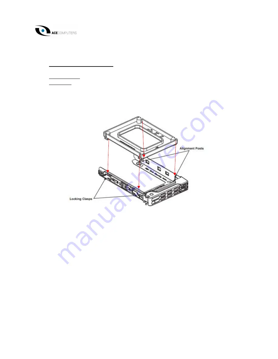
Type and number of fastenings: HDD = two locking clasps, SSD = two locking clasps.  


Tools required: None.   

Procedure:   

1.


Remove the dummy drive, which comes pre-installed in the drive carrier. Pull out the 

two locking clasps on the left outside of the carrier and lift out the dummy drive.  

2.


Position the drive above the carrier with the PCB side facing down and the connector 

end toward the rear of the carrier.  


3.


Tilt the drive to insert it onto the two posts on the right inside of the carrier.  

4.


Pull out the two spring locking clasps and allow the drive to sit fully in the carrier, then 

close them to secure the drive.  

5.


Insert the drive carrier into its bay, keeping the release button on the right. When the 

carrier reaches the rear of the bay, the release handle will retract.  

6.


Push the handle until it clocks into its locked position.  


Содержание PWB411

Страница 1: ...PWB411 and PWB421 Blade Servers User Manual Revision 1 0 Revision Date 03 18 2022...

Страница 2: ...nd found to comply with the limits for a Class A digital device pursuant to Part 15 of the FCC Rules These limits are designed to provide reasonable protection against harmful interference when the eq...

Страница 3: ...ning to EPEAT for the ACE Computers EPEAT registered servers Notes If you have any questions regarding this manual or server system please contact our support team through Ace Computers Support page h...

Страница 4: ...Chassis Cover 12 7 Batteries 13 Chapter 3 Installation Maintenance and Replacement Instructions 14 3 0 Accessing the System 14 3 1 Processor and Heatsink Replacement Installation 15 3 2 Memory Replace...

Страница 5: ...ystem and will continue to operate as intended for the entire lifecycle of the product The life expectancy of the server system is eight years on average If the server runs for 24 hours a day seven da...

Страница 6: ...ent and shall be disposed or recovered in compliance with Directive 2008 98 EC Please note All the illustrations in the below disassembly instructions are for demonstration only The system and compone...

Страница 7: ...ws SSD 1 Phillips screw Tools required Screwdriver with PH2 bit Procedure Step 1 HDD 3 5 Push the release button on the carrier Swing the handle fully Grasp the handle and pull the drive carrier out o...

Страница 8: ...ber of fastenings Two 2 latches per memory module Tools required None Procedure Press both release tabs on the ends of the memory module to unlock it Once the module is loosened remove it from the mem...

Страница 9: ...ere can be more than one processor per motherboard Type and number of fastenings Four 4 T30 Torx screws Tools required Screwdriver with T30 Torx bit Procedure Remove the screws as marked in the illust...

Страница 10: ...ircuit board that is greater than 10 sq cm and should be disposed or recovered in compliance with Directive 2008 98 EC A lithium battery resides on the motherboard The battery must be removed separate...

Страница 11: ...One 1 socket located on the motherboard and one 1 plastic plug Tools required None Procedure Remove the plastic plug from the SSD Motherboard Carefully pull the SSD card up and away from the Socket t...

Страница 12: ...2 3 the size of the entire top as noted in the illustration below Type and number of fastenings One 1 Phillips Head Screw Tools required Phillips Head Screw Driver Procedure To remove the cover remov...

Страница 13: ...hium battery resides on the motherboard The battery must be removed from separately from the motherboard and shall be disposed or recovered in compliance with Directive 2008 98 EC Removal instructions...

Страница 14: ...em Please follow the procedures given in each section Additional information regarding replacement components availability can be found in Chapter 5 below 3 0 Accessing the System The blade cover can...

Страница 15: ...U socket The Processor Carrier Assembly The processor carrier assembly is comprised of the processor and the processor carrier 1 Hold the processor with the land grid array LGA gold contacts facing do...

Страница 16: ...y press it down as shown below 4 Align the CPU keys on the processor A B with those on the carrier a b as shown below 5 Carefully place one end of the processor under latch 1 on the carrier and then p...

Страница 17: ...he heatsink over with the thermal grease facing up Note the tow triangle cutouts A B located at the diagonal corners of the heatsink as shown in the drawing below 2 On the processor carrier assembly f...

Страница 18: ...Date 3 18 2022 Installing the PHM into the CPU Socket 1 Remove the plastic protective cover from the CPU socket Gently squeeze the grip tabs then pull the cover off 2 Locate the threaded fasteners a...

Страница 19: ...3 4 are in the unlatched position as shown 5 Align nut A next to the triangles and pin 1 on the heatsink with threaded fastener a on the CPU socket Also align nuts B C D on the heatsink with threaded...

Страница 20: ...lbf in 3 2 Memory Replacement Installation Type and number of fastenings Two 2 latches per memory module Tools required None Procedure 1 Once you have followed the entire disassembly instructions und...

Страница 21: ...my drive 2 Position the drive above the carrier with the PCB side facing down and the connector end toward the rear of the carrier 3 Tilt the drive to insert it onto the two posts on the right inside...

Страница 22: ...Tools required None Procedure 1 Use industry standard anti static equipment such as gloves or wrist strap and follow precautions to avoid damage caused by ESD 2 Insert the SSD into the socket on the m...

Страница 23: ...arts or product service for your system for self replacement or for on site replacement please visit https acecomputers com support and fill out the Ace Computers Support Request form If phone assista...

Отзывы: