


Units with Packaged DX
1. Evaporator Coil Maintenance
Check for cleanliness - clean if required
2. Condenser Coil Maintenance
Check for cleanliness - clean if required
3. Condensate Drain
Inspect and clean - refill with water
4. Condensing Fan Blades and Motors
Check for cleanliness
Check all fasteners for tightness
Check for fatigue, corrosion and wear
Maintenance Procedures:
Lubrication
Check all moving components for proper lubrication.
Apply lubricant where required. Any components
showing excessive wear should be replaced to
maintain the integrity of the unit and ensure proper
operation.
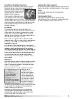
Dampers
Check all dampers to ensure they open and close
properly and without binding. Backdraft dampers can
be checked by hand to determine if blades open and
close freely. Apply power to motorized dampers to
ensure the actuator opens and closes the damper as
designed.
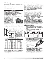
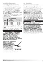
Fan Belts
Belts must be checked on a regular basis for wear,
tension, alignment and dirt accumulation. Premature
or frequent belt failures can be caused by improper
belt tension (either too loose or too tight) or
misaligned sheaves. Abnormally high belt tension or
drive misalignment will cause excessive bearing loads
and may result in failure of the fan and / or motor
bearings. Conversely, loose belts will cause squealing
on start-up, excessive belt flutter, slippage and
overheated sheaves. Both loose and tight belts can
cause fan vibration.
Routine Maintenance
DANGER
Electric shock hazard. Can cause injury or death.
Before attempting to perform any service or
maintenance, turn the electrical power to the unit
to OFF at disconnect switch(es). Unit may have
multiple power supplies.
CAUTION
Use caution when removing access panels or other
unit components, especially while standing on a
ladder or other potentially unsteady base. Access
panels and unit components can be heavy and
serious injury may occur.
This unit requires minimal maintenance to operate
properly. To ensure proper operation and longevity, the
following items should be completed. The items in this
list assume a relatively clean air environment, and may
require attention more frequently in a dusty or dirty
area. If this unit contains an indirect gas-fired heater,
refer to the Installation, Operation and Maintenance
manual provided with the unit for maintenance
purposes. A Certified Technician should complete all
refrigerant systems checks.
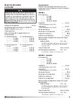
Maintenance Frequency:
Monthly
1. External Filter
Check for cleanliness – clean if required
2. Internal Filters
Check for cleanliness – replace if required
3. Condensate Drain (if applicable)
Inspect and clean – refill with water
4. Bearings
Lubricate per the schedule in the Fan Bearings
section
Semi-Annually
1. Fan Belts
Check for wear, tension, alignment
2. Check pulleys, bearings and motor for wear
3. Bearings
Lubricate per the schedule in the Fan Bearings
section
Annually
It is recommended that the annual inspection and
maintenance occur at the start of the cooling season.
After completing the checklist, follow the unit start-
up checklist provided in the manual to ensure the
refrigeration system operates in the intended matter.
1. Lubrication
Apply lubrication where required
2. Dampers
Check for unobstructed operation
3. Motors
Check for cleanliness
4. Fan Belts
Check for wear, tension, alignment
5. Blower Wheel & Fasteners
Check for wear, tension, alignment
Check all fasteners for tightness
Check for fatigue, corrosion, wear
6. Bearings
Lubricate per the schedule in the Fan Bearings
section
7. Door Seal
Check if intact and pliable
8. Wiring Connections
Check all connections for tightness
9. Cabinet
Check entire cabinet—inside and out—for dirt
buildup or corrosion. Remove accumulated dirt,
remove any surface corrosion and coat the area
with appropriate finish.
36
Model MPX Make-Up Air Unit
Model XMPX Make-Up Air Unit