


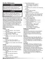

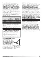

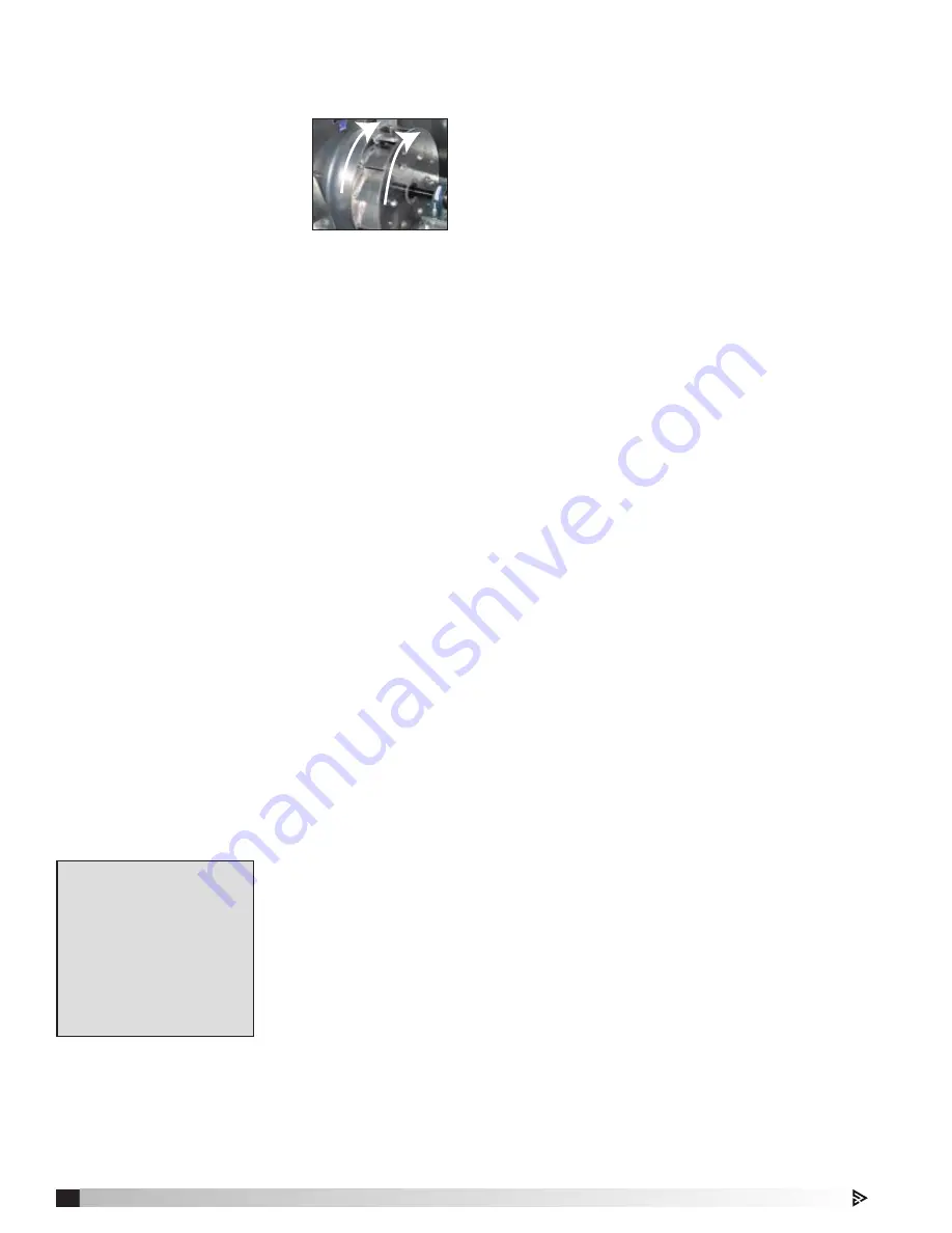
Fan Wheel Rotation Direction
Blower access is labeled on unit. Check for proper
wheel rotation by momentarily energizing the fan.
Rotation is determined by viewing
the wheel from the drive side and
should match the rotation decal
affixed to the fan housing.
If the wheel is rotating the wrong
way, direction can be reversed by
interchanging any two of the three
electrical leads. Check for unusual
noise, vibration or overheating of the bearings. Refer
to the Troubleshooting portion of this manual if a
problem develops.
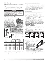
Fan RPM
The supply fan has been set at the factory for
optimum speed to meet specified air volume. The fan
is belt-driven and the basic configuration includes
fixed pulleys. To adjust fan RPM, it is necessary to
replaced the fixed pulleys with other fixed pulleys or
with adjustable multi-groove pulleys.
Some units are supplied with an optional variable
frequency drive (VFD) to control the fan motor speed.
To change motor RPM, consult the VFD manual
supplied with the unit.
Any increase in fan speed represents a substantial
increase in load on the motor. Always check the motor
nameplate when changing the fan RPM and verify
that the amp draw resulting from the change does not
exceed the motor rating. All access doors, except the
control center door, must be installed during testing.
Do not operate units with access doors open or
without proper ductwork in place as the fan motors
will overload.
Vibration
Excessive vibration may be experienced during initial
start-up. Left unchecked, excessive vibration can
cause a multitude of problems, including structural
and / or component failure.
The most common sources of vibration are listed.
Many of these
conditions can be
discovered by careful
observation. Refer to
the Troubleshooting
section of this manual
for corrective actions.
If observation cannot
locate the source of
vibration, a qualified
technician using vibration analysis equipment should
be consulted. If the problem is wheel unbalance,
in-place balancing can be done.
Generally, fan vibration and noise is transmitted
to other parts of the building by the ductwork. To
eliminate this undesirable effect, the use of heavy
canvas connectors is recommended.
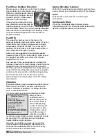
Centrifugal Airfoil
Rotation Direction
Spring Vibration Isolators
Verify that any optional spring vibration isolators have
been removed. See Installation portion of this manual.
Coils
Leak test the thermal system to ensure tight
connections.
Condensate Drain
Check the condensate drain to ensure proper
installation and that it is filled with water before start-
up. See Installation portion of this manual.
Vibration Causes
Wheel Unbalance
Drive Pulley Misalignment
Incorrect Belt Tension
Bearing Misalignment
Mechanical Looseness
Faulty Belts
Drive Component Unbalance
Poor Inlet / Outlet Conditions
Foundation Stiffness
26
Model MPX Make-Up Air Unit
Model XMPX Make-Up Air Unit