background image

50

1/2

20,000

50

3/4

30,000

50

1

40,000

75

1/2

13,333

75

3/4

20,000

75

1

26,666

75

1 1/2

40,000

71816-02, -06, -09, -13

100

1/2

10,000

100

3/4

15,000

100

1

20,000

100

1 1/2

30,000

100

2

40,000

150

3/4

10,000

150

1

13,333

150

1 1/2

20,000

150

2

26,666

150

3

40,000

182TC

12.25:1

260374-03

71867

71868

71869

71870

71816-03, -07, -10, -14

200

1

10,000

71816-01, -05, -08, -12

200

1 1/2

15,000

200

2

20,000

200

3

30,000

182TC

12.25:1

260374-03

71867

71868

71869

71870

71816-03, -07, -10, -14

250

1 1/2

12,000

250

2

16,000

250

3

24,000

71870

71816-03, -07, -10, -14

250

5 *

40,000

71870 *

71816-04, -07, -11, -14

300

1 1/2

10,000

300

2

13,333

300

3

20,000

71870

71816-03, -07, -10, -14

300

5 *

33,333

71870 *

71816-04, -07, -11, -14

260830-17

260998-040

260830-9

260998-036

260830-13

260998-038

260830-18

260998-040

260830-9

260998-036

260830-12

260998-038

260830-15

260998-038

143TC

71780

71780

71780

71780

71816-01, -05, -08, -12

71816-01, -05, -08, -12

71816-02, -06, -09, -13

71816-01, -05, -08, -12

71816-02, -06, -09, -13

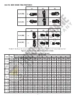
M9C CATALOG SPEEDS - HP, REDUCER, MOTOR, &  BRAKE SPECIFICATIONS

SINGLE

SPEED

SINGLE

SHAFT

TWO

SPEED

SINGLE

SHAFT

SINGLE

SPEED

DOUBLE

SHAFT

NOMINAL

SPEED

(FPM)

HORSE

POWER

(HP)

MAX.

LOAD

(LBS)

TWO

SPEED

DOUBLE

SHAFT

DRIVE

SPROCKET

& CHAIN

* 71870 (5Hp Only) - IS A MODIFIED 213TC FRAME WITH A 182TC STYLE MOUNT.

OPTIONAL

BRAKE

CHOICES

REDUCER

RATIO

REDUCER

ASS'Y

PART NO.

1800

SINGLE

SPEED

OR

1800/600

TWO

SPEED

MOTOR

SPEED

(RPM)

DRIVE PARTS OPTIONS

FRAME

SIZE

143TC

143TC

143TC

143TC

143TC

182TC

143TC

182TC

37.06:1

37.06:1

37.06:1

12.25:1

12.25:1

12.25:1

12.25:1

12.25:1

12.25:1

260374-01

260374-01

260374-01

260374-02

260374-02

260374-02

260374-03

260374-02

260374-03

71777

71778

71779

71777

71778

71779

71867

71867

71816-01, -05, -08, -12

71777

71778

71779

71777

71778

71779

71780

71780

71780

71778

71779

71777

71778

71779

71816-02, -06, -09, -13

71816-02, -06, -09, -13

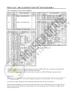
P

A

R

T

S

 L
IS
T

 -

 M9

C

 L
O
U

D

E

N

 MO

T

O
V

E

Y

O
R

®

 D
R

IV
E

 A
S

S

E

MB

L

Y

71868

71869

71868

71869

71777

71778

71779

71816-02, -06, -09, -13

71777

Содержание LOUDEN 200 Series

Страница 1: ......

Страница 2: ......

Страница 3: ......

Страница 4: ......

Страница 5: ......

Страница 6: ......

Страница 7: ......

Страница 8: ......

Страница 9: ...FIGURE 8 FIGURE 9 FIGURE 10 FIGURE 11...

Страница 10: ......

Страница 11: ......

Страница 12: ......

Страница 13: ......

Страница 14: ......

Страница 15: ......

Страница 16: ......

Страница 17: ......

Страница 18: ......

Страница 19: ......

Страница 20: ......

Страница 21: ......

Страница 22: ......

Страница 23: ......

Страница 24: ......

Страница 25: ......

Страница 26: ......

Страница 27: ......

Страница 28: ......

Страница 29: ......

Страница 30: ......

Страница 31: ......

Страница 32: ......

Страница 33: ......

Страница 34: ......

Страница 35: ......

Страница 36: ......

Страница 37: ......

Страница 38: ......

Страница 39: ......

Страница 40: ......

Страница 41: ......

Страница 42: ......

Страница 43: ......

Страница 44: ......

Страница 45: ......

Страница 46: ......

Страница 47: ......

Страница 48: ......

Страница 49: ......

Страница 50: ......

Страница 51: ......

Страница 52: ......

Страница 53: ......

Страница 54: ......

Страница 55: ......

Страница 56: ......

Страница 57: ......

Страница 58: ......

Страница 59: ......

Страница 60: ......

Страница 61: ......

Страница 62: ......

Страница 63: ......

Страница 64: ......

Страница 65: ......

Страница 66: ......

Страница 67: ......

Страница 68: ......

Страница 69: ......

Страница 70: ......

Страница 71: ......

Страница 72: ......

Страница 73: ......

Страница 74: ......

Страница 75: ......

Страница 76: ......

Страница 77: ......

Страница 78: ......

Страница 79: ......

Страница 80: ......

Страница 81: ......

Страница 82: ......

Страница 83: ......

Страница 84: ......

Страница 85: ......

Страница 86: ......

Страница 87: ......

Страница 88: ......

Страница 89: ......

Страница 90: ......

Страница 91: ......

Страница 92: ......

Страница 93: ......

Страница 94: ......

Страница 95: ......

Страница 96: ......

Страница 97: ......

Страница 98: ......

Страница 99: ......

Страница 100: ......

Страница 101: ......

Страница 102: ......

Страница 103: ......

Страница 104: ......

Страница 105: ......

Страница 106: ......

Страница 107: ......

Страница 108: ......

Страница 109: ...eration maintenance and parts manual 69879 Supplement SEPTEMBER 2009 supplemental instruction and parts manual pages for 6 1 2 inch diameter wheel trolleys These pages are to be used in conjunction wi...

Страница 110: ...ded spare parts 2 2 2 1 2 1 1 211661 260801 260434 260790 210021 210907 260225 1 1 ITEM NO PART NUMBER DESCRIPTION QTY 280866 260049 1 210410 2 WHEEL TROLLEY ASSEMBLY 6 1 2 FLANGED WHEELS 7 500 TROLLE...

Страница 111: ...TROLLEY ASSEMBLY 6 1 2 FLANGELED WHEELS 15 000 TROLLEY CAPACITY 3 25 AND 3 33 OPERATING FLANGE WIDTH 2 ITEM NO PART NUMBER DESCRIPTION QTY 260238 COMPLETE TROLLEY ASSEMBLY Part No 265178 15 000 trolle...

Страница 112: ...7 210407 Lockwasher 1 4 213532 Thrust Bearing 1 8 211547 Hex Nut 1 Recommended spare parts 4 WHEEL MONORAIL TROLLEY ASSEMBLY 6 1 2 FLANGED WHEELS 15 000 TROLLEY CAPACITY 3 25 AND 3 33 OPERATING FLANGE...

Страница 113: ...DE GUIDE ROLLERS 7 500 TROLLEY CAPACITY 3 25 OPERATING FLANGE WIDTH COMPLETE TROLLEY ASSEMBLY Part No 280312 7 500 trolley capacity 1 1 ITEM NO PART NUMBER DESCRIPTION QTY 280359 260049 260434 260837...

Страница 114: ...Part No 265177 15 000 trolley capacity 280312 Recommended spare parts 1 1 210238 213613 1 WHEEL TRAMBEAMTM HEAVY RAIL CRANE TROLLEY ASSEMBL 6 1 2 FLANGELESS WHEELS AND SIDE GUIDE ROLLERS 15 000 TROLLE...

Страница 115: ...4 213532 Thrust Bearing 1 8 211547 Hex Nut 1 Recommended spare parts 4 WHEEL TRAMBEAMTM HEAVY RAIL MONORAIL TROLLEY ASSEMBLY 6 1 2 FLANGELESS WHEELS AND SIDE GUIDE ROLLERS 15 000 TROLLEY CAPACITY 3 2...

Страница 116: ...211547 210868 2 2 1 2 1 Recommended spare parts 1 1 210410 211661 260801 213674 1 1 260434 260837 210021 210907 260225 COMPLETE TROLLEY ASSEMBLY Part No 280310 7 500 trolley capacity ITEM NO PART NUM...

Страница 117: ...LLEY ASSEMBLY 6 1 2 FLANGELESS WHEELS AND SIDE GUIDE ROLLERS 15 000 TROLLEY CAPACITY 3 33 OPERATING FLANGE WIDTH 2 ITEM NO PART NUMBER DESCRIPTION QTY 260238 COMPLETE TROLLEY ASSEMBLY Part No 265176 1...

Страница 118: ...er 1 4 213532 Thrust Bearing 1 8 211547 Hex Nut 1 Recommended spare parts ITEM NO DESCRIPTION 4 WHEEL TROJANTRACKTM MONORAIL TROLLEY ASSEMBLY 6 1 2 FLANGELESS WHEELS AND SIDE GUIDE ROLLERS 15 000 TROL...

Страница 119: ...damages to anyone beyond the cost of replacement of the goods sold hereby M9C Motoveyor supplemental parts manual This equipment should not be installed operated or maintained by any person who has no...

Страница 120: ...14 16 15 7 19 20 20 21 19 22 23 6 12 11 10 10 24 25 27 26 28 29 30 33 31 32 36 35 34 8 6 37 6 7 38 39 40 18 42 17 INCLUDED WITH WHEEL ASS Y PARTS LIST M9C LOUDEN MOTOVEYOR DRIVE ASSEMBLY M9C LOUDEN MO...

Страница 121: ...the chart labeled M9C CATALOG SPEEDS HP REDUCER MOTOR BRAKE SPECIFICATIONS 38 4 GUIDE ROLLER SIDE PLATE CARRIER YOKE PIN ASS Y W COTTER PIN BRACKET S G R FLANGE BEARING SPACER KEY 3 8 x 3 8 x 1 DRIVE...

Страница 122: ...71780 71816 01 05 08 12 71816 01 05 08 12 71816 02 06 09 13 71816 01 05 08 12 71816 02 06 09 13 M9C CATALOG SPEEDS HP REDUCER MOTOR BRAKE SPECIFICATIONS SINGLE SPEED SINGLE SHAFT TWO SPEED SINGLE SHA...

Страница 123: ...71778 23 71778 21 71778 22 200 71779 03 71779 13 71779 23 71778 01 200 208 230 460 71778 02 208 230 460 71778 12 71780 34 575 71778 11 71780 04 200 71780 14 71778 31 1 1 3 HP 71780 13 230 71780 23 460...

Страница 124: ...all be deemed waived by the Buyer unless Seller is notified in writing of the basis of such claims within 10 days after discovery of claimed defect and such discovery occurs within the warranted perio...

Страница 125: ...ystem and the potential hazards involved When risk to persons or property may be involved a holding device must be an integral part of the driven equipment beyond the speed reducer output shaft DODGE...

Страница 126: ...entilation Oil drain A6 A4 A3 A2 Horizontal Floor Mount Horizontal Wall Mount Vertical Wall Mount Motor Shaft Down Horizontal Wall Mount Vertical Wall Mount Motor Shaft Up Horizontal Ceiling Mount QUA...

Страница 127: ...3 3 2 1 5 3 0 1 4 H_68 1 1 1 0 5 3 9 1 9 3 1 1 5 3 7 1 8 2 1 1 0 2 2 1 1 2 3 8 1 8 8 7 4 1 5 3 2 5 6 8 3 2 5 7 2 7 4 9 2 3 3 3 6 1 7 8 5 4 0 5 5 2 6 8 5 4 0 5 5 2 6 5 1 2 4 H_88 1 1 6 0 8 8 0 3 8 5 3...

Страница 128: ...eral Oil 220 Mobilgear 600 XP 220 standard factory fill 20 F to 50 F 29 C to 13 C Synthetic Oil 68 Mobil SHC 626 10 F to 115 F 23 C to 46 C Synthetic Oil 220 Mobil SHC 630 30 F to 140 F 0 C to 60 C Sy...

Страница 129: ...flow of air around the motor Good access to gear reducer and motor for maintenance A flat level rigid steel mounting surface All four feet of the foot mounted unit must be evenly supported The flange...

Страница 130: ...s coupling half is mounted on the reducer shaft such that the shaft extends the complete length of the coupling bore Insert the coupling spider properly into the coupling jaws The DODGE QUANTIS ILH C...

Страница 131: ...2 Nm 0 140 M6 132 lb in 15 Nm M4 27 lb in 3 Nm 180 24 28 M5 18 lb in 2 Nm 0 180 M8 312 lb in 35 Nm M6 90 lb in 10 Nm 210 28 38 M6 42 lb in 4 8 Nm 0 210 M10 600 lb in 68 Nm M8 220 lb in 25 Nm 250 38 4...

Страница 132: ...ghtening Torque Nm Tightening Torque ft lb 38 1 M8 25 18 2 3 M8 25 18 48 1 M8 25 18 2 3 M10 50 37 68 1 M10 50 37 2 3 M12 90 66 88 1 M12 90 66 2 3 M16 210 155 108 2 3 M16 210 155 128 2 3 M16 210 155 14...

Страница 133: ...others by observing all safety information Failure to comply with instructions could result in personal injury and or property damage Retain instructions for future reference Inertia of Dimensions Num...

Страница 134: ...k it in the open position and tag it to prevent unexpected application of power 5 When working on the brake be sure the load is completely removed secured or blocked to prevent injury or property dama...

Страница 135: ...friction disc together This permits free rotation of the shaft WARNING Observe proper safety precautions in applications where a brake failure would allow the load to move in such a manner as to inju...

Страница 136: ...100 adjustment is required Any delay in adjusting the magnet air gap will result in eventual loss of torque Refer to Fig 3 1 To adjust remove cover locknuts 22 and cover 20 to expose square head wear...

Страница 137: ...Re assembly of operator assembly 15 Refer to Figs 3 and 9 Capscrew 16 is shown in Fig 9 and not Fig 3 Turn two screws 15H counterclockwise five turns Place operator assembly onto brake bracket 2 and i...

Страница 138: ...le operator assembly to brake bracket Set magnet air gap A and set torque springs 15S to 1 as shown in Fig 3 Pivot Stud Adjustment CAUTION Load to be removed or blocked Brake will be inoperative durin...

Страница 139: ...erclockwise 1 4 turn and try again 3 If the release knob 3 does not return to its normal position automatically turn screw 5 clockwise 1 4 turn and try again NOTE You may have to repeat Steps 2 or 3 t...

Страница 140: ...w motor it is important to consult the correct diagram for spring location Qty of Parts Item Part determined by no of rotating discs No Description No 1 2 3 4 1 Spring silver G060350 001 2 2 2 2 Sprin...

Страница 141: ...replacement is not required adjust air gap Refer to Wear Adjustment section 3 Hub positioned incorrectly 3 Relocate hub 1 and key if required Refer to Installation section 4 Bake is manually released...

Страница 142: ...REPLACEMENT PARTS ILLUSTRATION Figure 9 10 15J 15K 22 19 150 15P 15N 15M 150 15L 151 15F 17 18 CLINCH NUT INCLUDED IN ITEM 15F 15C 15R 15B 12 13 l SHADING COIL INCLUDED IN ITEM 15A 3 6 4 2...

Страница 143: ...d 1 4 20 x 1 1 2 lg W002003 001 2 15I Roll pin 5 32 dia x 3 8 lg W005003 098 1 15J Armature lamination assembly G060788 001 1 15K Armature shock mount G060808 003 1 15L Armature spacer G060798 002 2 1...

Страница 144: ...and proper maintenance for a period of twelve months from date of shipment If within such period any such products shall be proved to Seller s reasonable satisfaction to be defective such products sha...

Отзывы: