background image

Sharp SmartPunch Pro Installation Manual 

8


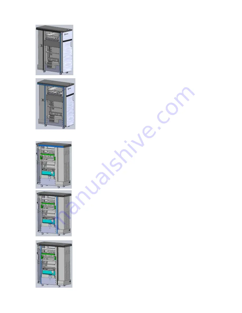
Apply another longer strip to the side cover. 
Align it so that the long edge of the foam is in 
line with the end of the horizontal foam. 


Exit side complete 

4.2 Paper Entrance Side (Main Unit Side) 


Apply the remaining short strip to the Top cover. 
Align it so that  

a.  the short edge of the foam lines up with 

the rear edge of the Top cover and b. 

b.  the long edge of the foam lines up with 

the bottom edge of the Top cover. 


Apply one of the two remaining long strips to the 
side of the rear cover.  Align it so that:  

a.  the long edge of the foam lines up with 

the edge of the rear cover and 

b.  the short edge of the foam touches the 

horizontal sound foam in the top. 


Apply the last remaining long strip to the left side 
of the main unit side of the SmartPunch Pro along 
the flange of the front frame touching the 
horizontal foam on the top. 

Содержание GBC Sharp SmartPunch Pro

Страница 1: ...Sharp SmartPunch Pro Installation Manual 1 Sharp SmartPunch Pro Installation Manual ACCO Brands Inc Four Corporate Drive Lake Zurich IL 60047 www acco com...

Страница 2: ...llation Manual 2 Contents Page 1 Recommendations and Pre requisites 3 2 Unpacking 3 3 Cable Connections 3 4 Installing the Sound Deadening Foam 6 5 Docking Bracket Installation 8 6 Leveling Height Adj...

Страница 3: ...installation of the SmartPunch Pro See below for content details Inspect for any concealed damage to the unit If there is evidence of concealed shipping damage contact the shipping carrier immediatel...

Страница 4: ...X ST10 High Capacity Stacker 3 2 MX RB18 Curl correction unit 3 1 Cable connections a i Remove the finisher rear cover and plug the 7 pin communication cable to CN145 on the finisher board The communi...

Страница 5: ...measuring about 31mm in paper flow direction when used in conjunction with Inserter MX CF11 or High Capacity Stacker MX ST10 When connecting to the MX CF11 follow the procedure in d below before inst...

Страница 6: ...entrance paper guides provided with the SmartPunch Pro Use the shorter paper guide measuring about 24mm in paper flow direction when used in conjunction with Curl correction unit MX RB18 Install the p...

Страница 7: ...l the adhesive using the following steps as a reference 4 1 Paper Exit Side Finisher Side Apply one of the two shorter strips to the Top cover Align it so that a the short edge of the foam lines up wi...

Страница 8: ...nes up with the rear edge of the Top cover and b b the long edge of the foam lines up with the bottom edge of the Top cover Apply one of the two remaining long strips to the side of the rear cover Ali...

Страница 9: ...ection Unit MX CF11 Inserter Install as shown with the bracket marked R on the right side facing you as you look at the exit side of the upstream device pictures shown Install the bracket marked L on...

Страница 10: ...a reference 6 2 Adjusting the Casters a Using a 9 16 15mm open ended wrench loosen the jam nut s situated on the caster stud inside of the machine b Using the 9 16 15mm wrench rotate the caster stems...

Страница 11: ...artPunch Pro can be found on the front frame on the lower left corner shown left Turn the SmartPunch Pro on before the main unit The Punch icon shown right will appear automatically if the connections...

Отзывы: