glued into the end of a pipe to act as an installation handle. The cable feeds up through the pipe and
emerges through a notch at the upper end. The pipe can then be capped off at the upper end to prevent
water ingress. The pipe/sensor assembly can them be inserted into a hole that was drilled using a 34
mm flat-bottomed auger. A mallet can be used to pound the top of the pipe and force the sensor
waveguide into the undisturbed soil at the bottom of the hole. With the flat-bottomed hole the
sideways bias on the waveguide rods is minimal thus allowing the rods to enter the soil in a parallel
alignment. This method of installation is generally easier than the trench method used with the
TDR315H.
TDR310H Optimum Application:
All types of soils are suitable environments for TDR310H measurements. Its sampling volume is only
about ¼ of the TDR315H but that is the tradeoff for easier installation. In addition the TDR310H has a
lower impedance waveguide with a shorter length. This makes it particularly suited to soils with high
salt content
–
up to 15 dS/m saturated paste extraction.
TDR305H Description, Installation and Optimum Application:
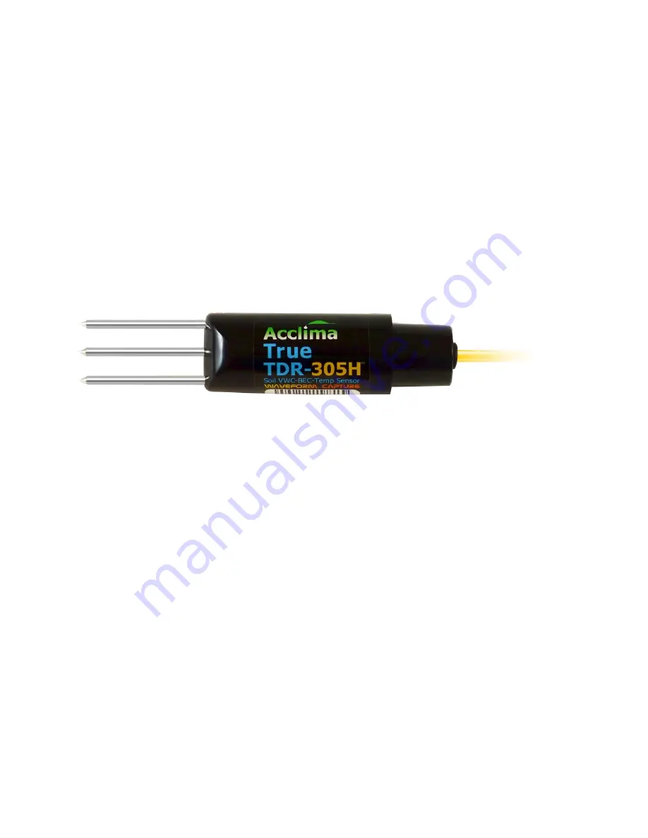
The TDR305H was developed from the TDR310H as a measurement solution for soils with exceedingly
high salt levels. It provides credible measurements in soils with saturated paste extraction EC levels up
to 20 dS/m. Because of its low sampling volume the TDR310H or TDR315H would be better choices for
applications where salt is not a problem.
Sensor Setup and Connection:
Acclima’s TDR sensors use the industry standard SDI
-12 communications protocol and are compatible
with any Data Recorder, Reader or Wireless Device that incorporates a compliant SDI-12 Port. The
sensor cable includes 3 wires. The red wire is the power line. The blue wire is the bi-directional data line
and the white wire is the common for both the data and power.
When sensors are installed to a data recorder or other reading device there are two steps that must be
taken to insure successful communications. The first is the hardware connection. The second is the
sensor addressing. The SDI-12 protocol uses address to distinguish between multiple sensors. These
must be set uniquely for each sensor wired to a common SDI-12 recorder or reader. Valid addresses are
the numerals 0 through 9, the lower case characters a through z and the upper case characters A
through Z for total of 62 possible addresses. The sensors are shipped from the factory with the default
address ‘0’.
Setting Sensor Addresses:


