TVCC75100TVCC75200
User manual
Version
6/2011
Original English user manual. Keep for future use.
Страница 1: ...TVCC75100 TVCC75200 User manual Version 6 2011 Original English user manual Keep for future use...
Страница 2: ...are registered trademarks All rights reserved If you have any questions please contact your installer or your local dealer Disclaimer This user manual was prepared with greatest care If you should not...
Страница 3: ...achinery or loudspeakers x The camera should not positioned with opened iris towards the sun this can lead to the destruction of the sensor x the camera may not be installed on unstable surfaces Gener...
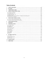
Страница 4: ...E CONTROL DEVICES 60 5 1 CONTROL USING OPERATOR PANEL TV7605 60 5 2 CONTROL USING TV3000 TV3031 RECORDERS 60 6 QUICK OPERATING KEYS 61 7 DIAGNOSTIC 63 8 OSD MENU SETTING 64 8 1 OSD MENU TABLE 64 8 2 D...
Страница 5: ...tal Zoom x Up to 560 TVL resolution x Password protection x Low Noise Technology for extremely quiet movement with 0 024 accuracy x Slip ring for long life time 20 million rotate ring tested x Advance...
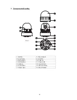
Страница 6: ...ponents Naming 1 Bubble 8 Video Output 2 Lock Screw 9 Loop RX 3 DIP Switch 1 10 Loop TX 4 DIP Switch 2 11 Power LED 5 Camera 12 Aux terminal 6 Lock Holder 13 Alarm terminal 7 Power input 14 Mount Hold...
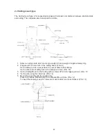
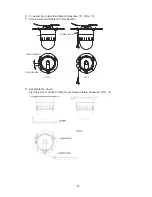
Страница 7: ...r body from the lower body by turning counterclockwise FIG 3 4 2 After separating set DIP switches Refer to the page 78 3 To assemble camera body rotate the upper body clockwise to assemble both bodie...
Страница 8: ...rol 3 TX TX transmits data signal received from RX to other equipment TX is convenient terminal for daisy chain connection 4 RX RX receives control signal from controller or DVR 5 Video out BNC connec...
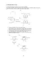
Страница 9: ...145 mm hole in the ceiling board FIG 9 Fix the safety wire to a suspension to prevent camera from falling Fix the other side of safety wire to the safety wire hole FIG 10 3 Fix the Ceiling Mount to th...
Страница 10: ...ate the Camera clockwise 10 FIG 13 7 Screw up Lock Holders with screws M3 8 Assemble the Cover Fix three Cover Locks to three Cover Holes rotating clockwise FIG 15 10 FIG 13 FIG 14 SCREW M 3 0 LOCK HO...
Страница 11: ...camera will be visible 1 Prepare an 190 mm hole in the ceiling board Fix the safety wire to a suspension to prevent camera from falling Other side of safety wire is fixed to the safety wire hole FIG...
Страница 12: ...Fit the indoor adapter exactly on the drill holes and fasten the adapter with appropriate screws Use nuts to prevent slipping 4 Connect the individual lines to one another using the cable strap and g...
Страница 13: ...bracket In combination with Indoor Adaptor TV7608 it is possible to use Dropped ceiling mount bracket TV7609 or Goose neck mount bracket TV7612 indoor These optional accessories are not in scope of de...
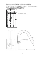
Страница 14: ...ables can be guided directly through the retaining plate or through the side cable feed 5 Screw one of the two threaded rings included in the indoor adapter s delivery scope onto the thread of the goo...
Страница 15: ...66 It is possible to use the outdoor housing with a Wall mount bracket scope of delivery a Dropped ceiling mount bracket and or a Goose neck mount bracket For further information please refer to insta...
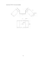
Страница 16: ...59 Dimensions TV7611 Corner mount adaptor...
Страница 17: ...ing actions 1 Connect the RS 485 lines to the interface for controlling on the HDVR 2 Link up the analogue camera to the software Refer to the operating manual for more details 3 Activate the Pan Tilt...
Страница 18: ...On Off in Digital Slow Shutter function 80 85 Preset Pattern Executing Pattern 1 6 86 Preset Auto Scan Executing Auto Scan 87 89 Preset Group Tour Executing Group Tour 1 3 90 Preset OSD Entering OSD...
Страница 19: ...0 Preset Preset Executing Preset 1 64 100 200 67 Preset Auto Flip Selectable On Off in Auto Flip mode 69 Preset DSS Selectable On Off in Digital Slow Shutter function 80 85 Preset Pattern Executing Pa...
Страница 20: ...sed to ID of camera not necessary for function ID is displayed at start up refer to page 78 according ID setting If No Tested is displayed the camera did not receive any signal from DVR or controller...
Страница 21: ...64 8 OSD Menu Setting 8 1 OSD Menu Table...
Страница 22: ...prior character from the right to left Space is displayed when appears 2 DOME SET RECOVER This feature allows the dome to activate the last specified operation auto scan group tour preset pattern or s...
Страница 23: ...er set as ENABLE Move joystick to the right or left direction to select ENABLE DISABLE The default setting is DISABLE and this feature can be enabled with 97 PRESET button 7 DOME SET LANGUAGE Several...
Страница 24: ...en PASSWORD and CONFIRM CANCELLED is displayed on the monitor and the menu will return to the previous page automatically if user fails 3 times x After setting a Password the operator has to type in m...
Страница 25: ...S A variety of system information is displayed at SYSTEM STATUS x Protocol and baud rate are shown due to the dip switch setting Refer to page 245 x Firmware version and upgrade date will change after...
Страница 26: ...factory default move joystick rightwards when cursor is at LOAD FACTORY SETTINGS to enter the above page x Move joystick to the right or left direction in order to select YES press FOCUS NEAR button...
Страница 27: ...cture detail by increasing gain of the camera and sharpening the edges in the picture The default seeting is 10 the aperture level is adjustable from 01 15 4 CAMERA SET DIGITAL ZOOM Move joystick righ...
Страница 28: ...ources has to be observed select WDR setting ON 8 CAMERA SET D N MODE IR filter is changeable due to the lighting conditions as AUTO NIGHT MODE DAY MODE The default setting is AUTO MODE Auto mode swit...
Страница 29: ...m the right to left Space is displayed when appears 3 PRESET PAN XXX X TILT XX X Press FOCUS FAR button in order to set preset position then use the joystick to the position which is needed memorized...
Страница 30: ...be set endless Move joystick rightwards in order to select ON The default setting is OFF 5 AUTO SCAN SPEED Auto scan speed can be adjusted from 05 per second up to 35 per second The default setting is...
Страница 31: ...ut it is possible to set up to group tours 8 1 TOUR SET TOUR NO Up to 8 group tours are available to set by the joystick 2 TOUR SET TOUR TITLE To set tour title select up to 16 characters moving Joyst...
Страница 32: ...S 7 TOUR SET SAVE To save the memorized data move joystick rightwards when cursor is at SAVE The cursor will automatically move to the next tour step then 8 TOUR SET EXIT Move joystick to the right to...
Страница 33: ...ogrammable patterns are available with 16 characters for title After setting the data of each pattern 81 88 PRESET buttons are working as Pattern 1 8 x Maxpro protocol provides 6 quick operation keys...
Страница 34: ...alarm inputs supports 3 different connection states NC Normally Close NO Normally Open or OFF disabled The default setting is OFF 3 ALARM SET ALARM ACT Alarm inputs can activate various surveillance...
Страница 35: ...the joystick to go to the start position of sector Press FOCUS FAR button again to escape 4 SECTOR SET SECTOR END To set end position of sector press FOCUS FAR button Use the joystick to go to the en...
Страница 36: ...0 10010100 41 00010010 72 11010000 11 01010100 42 10010010 73 00110000 12 11010100 43 01010010 74 10110000 13 00110100 44 11010010 75 01110000 14 10110100 45 00110010 76 11110000 15 01110100 46 101100...
Страница 37: ...3 01000111 226 00011110 120 01110101 174 11000111 227 10011110 121 11110101 175 00100111 228 01011110 122 00001101 176 10100111 229 11011110 123 10001101 177 01100111 230 00111110 124 01001101 178 111...
Страница 38: ...ve are used for Protocol Setting Factory Default Pelco D or Pelco P Auto detection DIP SW2 3rd 4th OFF OFF Pelco D or Pelco P ON ON Maxpro protocol 9 4 Baud Rate Setting The 7th 8th SW of DIP SW2 is u...
Страница 39: ...8 D 7 5 H 1 9 kg 5 lbs Stepper 811 H 508 V 410K 811 H 508 V 410K 795 H 596 V 470K TVCC75100 TVCC75200 VBS 1 0Vp p sync negative Y C Output ON OFF Optical 0 2Lux 50IRE 0 02Lux ICR On 0 01Lux ICR On 0 0...
Страница 40: ...83 147 0 134 0 Einheiten mm 190 0...