Abra AK-10 Скачать руководство пользователя страница 9

8

Transformers

Transformers in general are useful devices that assist in converting alternating current to either 

increasing or decreasing AC voltage. They achieve these results through the process of induction. 

A primary coil is feed with AC voltage, a non-conductive magnetic core or alternatively known 

as a ferrite core is the housing for the wires to coil onto. The secondary coil that is parallel to the 

primary coil which is not connected to the primary coil act as output for the transformer. The 

electromagnetic forces moves the electrons and creates a flow of current and voltage that is either 

higher or lower by the amount of windings that is in the primary and secondary wiring. If the 

primary coil has fewer wires than the secondary coil it becomes a step up transformer with a low 

current and high voltage output. In the case of the step down transformer the primary coil has 

more windings than the secondary coil with a low voltage and high current output.  

The formula used to calculate the Power of a device using the North American single phase power 

is calculated in terms of Watts. Power = Volt * Current * (kW actual load power/kVA apparent load 

power)

A Centered tapped transformer is what is currently supplied with this kit, they can be commonly 

found outside on the power poles. A center tapped transformer is essentially as the name implies, 

the  secondary  winding  is  wrapped  around  the  ferrite  housing  with  one  end  starting  from  the 

bottom, the other end at the top and the center tapped wire is located in the middle of the winding. 

Another interpretation can be seen as a pencil with wire wrapped on it, the wire starts at the eraser 

end and ends at the pencil tip. A center tapped wire is located in the middle of the pencil that is glue 

or fastened in at the center, almost like a potentiometer with a fixed wiper. This center cable acts 

as the reference cable to reference the voltage; however in the kit the center line acts as the return 

wire. 

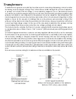
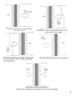
Here are some common wiring for transformers that are available in the market.

Common two wire in and 

out transformer

Center tapped transformer

(Either 16v from top to middle or 16v middle to 

bottom or 32 V across, same current)

Содержание AK-10

Страница 1: ...s abra electronics com U S Toll Free 1 800 717 2272 Can Toll Free 1 800 361 5237 18 Volts AC output and a Variable 18 volts DC output Up to 1 Amp in current output Simple component placement guide On...

Страница 2: ...oblueshooting FAQs 12 13 VIII About Us 14 Designed by Thushanth Sithambararajan Rev 1 0 1 Parts list 2x 220 F Capacitor C2 C3 2200 F Capacitor C1 DPDT Switch On On 2x 2 pin Terminal Block AC DC T0 220...

Страница 3: ...ndoffs 18 volts sine wave 18 volts adjustable DC PC mount potentiometer with fine precsion adjustment Included heatsink Specs Tools Required Pencil type soldering iron Solder 60 tin 40 lead recommende...

Страница 4: ...em into the place marker where they belong 3 Insert Components and bend the pins slighty to hold into place when soldering 4 Solder the pin with the soldering iron for tips on how to solder please rea...

Страница 5: ...d the two blue wires to the outside connections 10 Place on the LM317 the heat sink clip 11 Solder the terminal connection blocks and flick the switch to off position pointing downwards in reference t...

Страница 6: ...r degrees but they often come back to where they started For example the figure below the voltage offset is 0 volts The sine wave starts at 0 volts and will end at 0v the length of this period is 2 or...

Страница 7: ...imple matter of plotting it away from the origin by 90 as its starting point However if the period is 2 or 6 it can get messy quick ly by not knowing where to end A simple way to get over this is to c...

Страница 8: ...mathematically to find the midpoint of the AC voltage or current that is being provided during time lapse of the period The difference between RMS and Average is with the fact that RMS is the instanta...

Страница 9: ...lculate the Power of a device using the North American single phase power is calculated in terms of Watts Power Volt Current kW actual load power kVA apparent load power A Centered tapped transformer...

Страница 10: ...ormer parallel connection more current less voltage Dual input transformer parallel connection Very versatile for 110v or 220v application one transformer Dual input transformer series connection Dual...

Страница 11: ...e or half wave Full wave rectifiers Full wave rectifiers convert the entire waveform into one constant polarity at the output in essence they convert the AC to a DC wave In some sense a half wave rect...

Страница 12: ...current will adjust to meet the output required If you are scratching your head trying to understand how this is done recall ohm s law V I R Increase the current and keep the same resistance voltage g...

Страница 13: ...n power dissipation will explain the reason for overheating A temporary solution is to place a heat sink on the LM317 IC I have no voltage output Please check if the solder contacts were soldered prop...

Страница 14: ...lease read the Capacitor subsection in the theory chapter Where can I mount this ThesideholesallowyoutomountthepowersupplywithABRAstandoffswhereeveryouplease alternatively you may purchase a plastic p...

Страница 15: ...ts all with affordable pricing Feel Free to call us on our toll free numbers indicated below You will be greeted with our knowledgeable and courteous staff members You are also free to visit our websi...

Страница 16: ......

Отзывы: