Ablerex KRONOS Скачать руководство пользователя страница 48


46 


Recommended 1+1 parallel system configuration 

Bypass

Load

Mains


1+1 parallel 


Parallel 

Communication 

Cables 

Содержание KRONOS

Страница 1: ...KRONOS 208V 10 40kVAUPS Installation and Operation Manual...

Страница 2: ...tions 40 2 7 UPS Parallel Connections Option 44 3 Kronos Operation And Descriptions 48 3 1 Operating Mode 48 3 2 Online Operations 49 3 3 Manual Bypass Operation 49 3 4 Operating Processes 50 4 Contro...

Страница 3: ...afe operation The manual also provides troubleshooting assistance should an abnormal message or behavior occur Should an abnormal message not covered in this manual appear contact your local authorize...

Страница 4: ...batteries 9 For 30k 40k models The over current protection for the external battery circuit is to be provided by others 10 For 30k 40k models The maximum available fault current from the battery supp...

Страница 5: ...batteries remove jewelry such as wristwatches and rings or other metal objects When working on batteries should wear rubber gloves and boots Also must use tools with insulated handles and do not lay...

Страница 6: ...can radiate radio frequency energy and if not installed and used in accordance with the instruction manual may cause harmful interference to radio communications Operation of this equipment in a resid...

Страница 7: ...shown below 1 Input Breaker Switch 5 Static Switch 2 Manual Bypass Breaker 6 Charger Booster 3 Rectifier 7 Output Breaker 4 Inverter 8 Bypass Breaker 4 5 2 7 6 X20 X50 Battery Load ngle Input 1 3 4 5...

Страница 8: ...6 1 2 UPS Front View 10kVA Front View 1 2 3 260mm 890mm 69mm 1 Control Panel with Color LCD Touch Screen 3 Wheels for Positioning 2 Ventilation Grille...

Страница 9: ...7 15 20kVA Front View 3 410mm 977mm 72mm 1 2 1 Control Panel with Color LCD Touch Screen 3 Wheels for Positioning 2 Ventilation Grille...

Страница 10: ...8 30 40kVA Front View 1 Control Panel with Color LCD Touch Screen 3 Wheels for Positioning 2 Ventilation Grille 1 2 3...

Страница 11: ...9 10kVA Right Side View 850mm...

Страница 12: ...10 15 20kVA Right Side View 850mm...

Страница 13: ...11 30 40kVA Right Side View...

Страница 14: ...r Setting Switch for Parallel Communication 10 Status LED Indictors 11 EPO 12 Backfeed Protection 13 MBP Detector Please find the detail descriptions of above items on section 2 6 14 Manual Bypass Bre...

Страница 15: ...tting Switch for Parallel Communication 10 Status LED Indictors 11 EPO 12 Backfeed Protection 13 MBP Detector Please find the detail descriptions of above items on section 2 6 14 Bypass Input Breaker...

Страница 16: ...tatus LED Indictors 11 EPO 12 Backfeed Protection 13 MBP Detector Please find the detail descriptions of above items on section 2 6 14 Bypass Input Breaker 20 X20 External Battery Connection Terminals...

Страница 17: ...15 10kVA Internal Right View 1 1 Battery Tray...

Страница 18: ...16 15 20kVA Internal Right View 1 1 Battery Tray...

Страница 19: ...17 10kVA Internal Top View 1 SD Card Slot 2 Jumpers J1 J3 for each output contact The detailed descriptions of the above items are located in section 2 6 1 2...

Страница 20: ...18 15 20kVA Internal Top View 1 SD Card Slot 2 Jumpers J1 J3 for each output contact The detailed descriptions of the above items are located in section 2 6 1 2...

Страница 21: ...19 30 40kVA Internal Top View 1 SD Card Slot 2 Jumpers J1 J3 for each output contact Please find the detail descriptions of above items on section 2 6 1 2...

Страница 22: ...an environment with sparks smoke or gas to prevent arcing injury and fire hazards Avoid using dusty materials volatile gases or corrosive substances with a high salt content in the environment where t...

Страница 23: ...nd removing processes with the wheels installed Remove the packing materials and cut straps Remove and slide up the cardboard box 10kVA 15 20kVA 30 40kVA Unscrew the fasteners on the ramp kits located...

Страница 24: ...22 15 20kVA 30 40kVA...

Страница 25: ...on the pallet edge by fastening 4 screws in the pallet 10kVA Remove the UPS from the pallet by using the rails to slide the UPS forward onto a flat surface See the next figure when using a Fork Lift...

Страница 26: ...24 15 20kVA 30 40kVA...

Страница 27: ...25 Raise the wheel brakes to remove the UPS 10kVA 15 20kVA Wheel Brake Wheel Brake...

Страница 28: ...26 30 40kVA Block the wheel brakes to secure the UPS 10kVA Wheel Brake Wheel Brake...

Страница 29: ...27 15 20kVA 30 40kVA Wheel Brake Wheel Brake...

Страница 30: ...28 Follow this step to secure the UPS 10kVA 15 20kVA...

Страница 31: ...29 30 40kVA...

Страница 32: ...wed Keep at least 1000mm of clearance to the front of the UPS for air flow and future maintenance purposes Keep at least 300mm of clearance from the rear of the UPS for air flow space Keep at least 30...

Страница 33: ...nnection Positions The drawing below shows the positions of the power terminals Mains Output Battery Bypass 10kVA Power Terminal Positions 15 20kVA Power Terminal Positions Mains Bypass Output Battery...

Страница 34: ...20kVA 20kW 64 6A 55 5A 140 0A 30kVA 30kW 96 6A 85A 191 8A 40kVA 40kW 128 6A 113 4A 255 8A 220 V 10kVA 10kW 30 7A 26 2A 70 4A 15kVA 15kW 45 6A 39 4A 105 0A 20kVA 20kW 61 1A 52 5A 140 0A 30kVA 30kW 91 3...

Страница 35: ...Q 88 3 Lb in 1 The recommended maximum length of cabling is less than 10meters 2 Always over size neutral line N by 1 7 times of the phase line for non linear loads Minimum Recommended Circuit Breaker...

Страница 36: ...34 Electrical System Connections UPS with single input Load 3P N UPS with single input and isolation transformer Load 3P 3P N...

Страница 37: ...35 UPS with dual inputs Load 3P N 3P N UPS with dual inputs and isolation transformer Load 3P 3P N 3P 3P N Load 3P N 3P 3P N...

Страница 38: ...36 Load 3P 3P N 3P N Note You must install an isolation transformer on one of the inputs if the two power source are different UPS in parallel using separate battery Load 3P N...

Страница 39: ...37 UPS in parallel using a common battery Load 3P N...

Страница 40: ...38 UPS in parallel with an output transformer Do not use individual output transformers for each UPS A common output transformer must be used Load 3P N Load 3P N...

Страница 41: ...er switch is used first in sequence before turning on UPS Don t switch this OFF at any time while the UPS is operating Batt Start Battery Cold Start The UPS will start up using batteries when main inp...

Страница 42: ...contact 250 VAC 2 A 30 VDC 2 A There are 3 jumpers J1 J3 to set NC NO for each output contact To short the input contact to send a command to the UPS The user can change the definition for each contac...

Страница 43: ...Rate 57600bps Data Length 8 bits Stop Bit 1 bit Parity None This port is available for changing the settings of the UPS by setting software Paral 1 Paral 2 Parallel communication port Parallel communi...

Страница 44: ...in case of emergency Short this contact to turn off the UPS immediately Backfeed Trip The UPS provides a backfeed protection contact to trip the external electromechanical device for isolation from th...

Страница 45: ...n Slot 2 move the switch to SNMP position SW3 the switch for terminal resistor of parallel communication To ensure a proper parallel communication connection the selector switch on each of the additio...

Страница 46: ...sting for parallel operation system Parallel configuration must be performed by authorized and qualified technicians who are familiar with this the Kronos UPS Parallel cables must installed in order f...

Страница 47: ...45 Parallel communication cables connected are shown below...

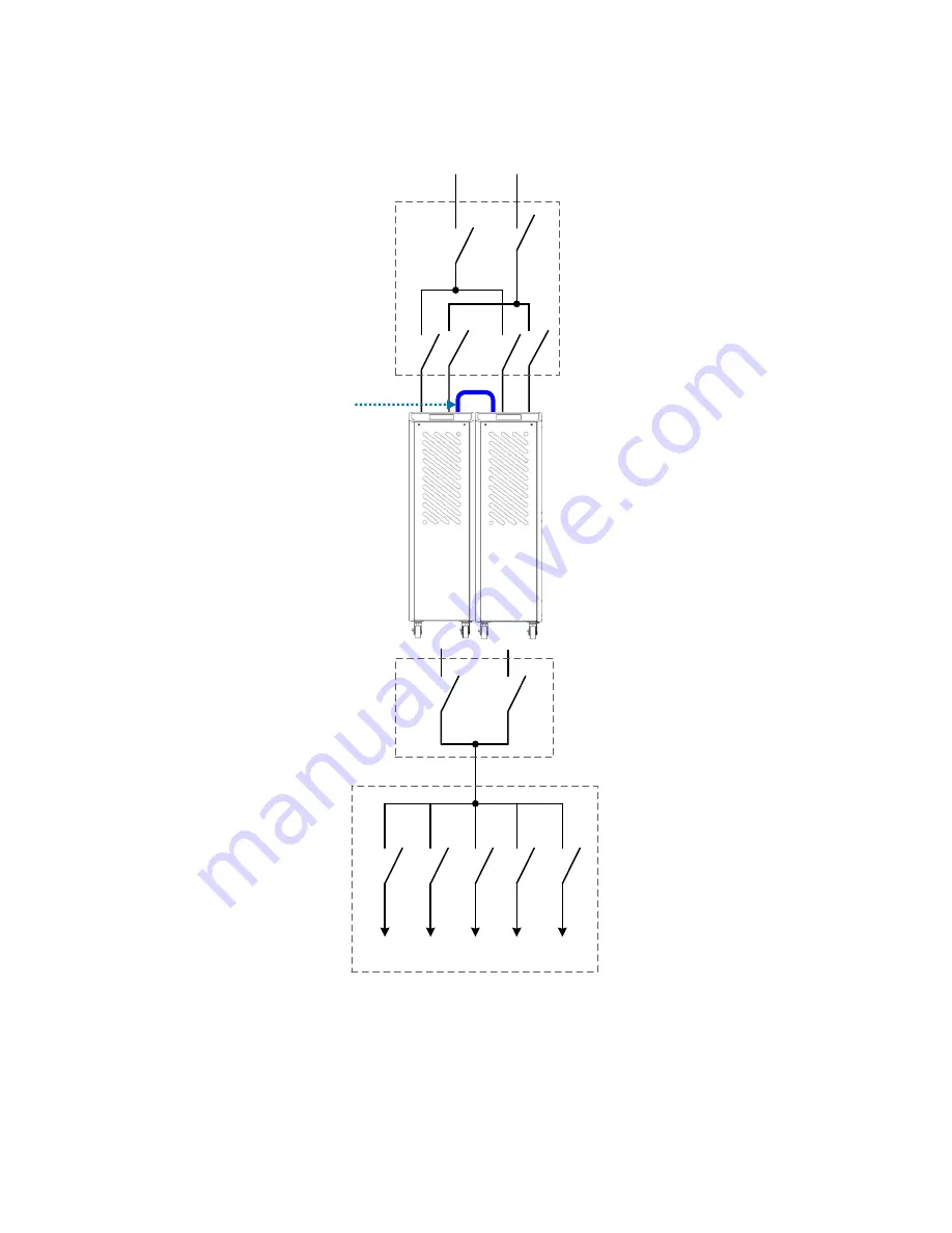
Страница 48: ...46 Recommended 1 1 parallel system configuration Bypass Load Mains 1 1 parallel Parallel Communication Cables...

Страница 49: ...47 Recommended N 1 parallel system configuration External Manual Bypass Switch Bypass Up to 6 UPS Units Load Mains Parallel Communication Cables...

Страница 50: ...g the same setup as VFI Mode Inverter is also kept ready to switch power supply modes at any time If VFI mode is set then power can be quickly routed from Bypass to Inverter Attention In ECO Mode the...

Страница 51: ...ply circuit switches from Inverter to the bypass output Battery Mode When the UPS detects a failure in the main power supply then power is provided from the battery instead The touch screen at the fro...

Страница 52: ...50 3 4 Operating Processes 10kVA 15 20kVA 30 40kVA...

Страница 53: ...Mains Input Breaker Switch and Bypass Input Breaker if equipped 3 Select Command Operation Normal Mode on LCD display 4 Return to the Mimic Display Wait for few minutes the rectifier will have started...

Страница 54: ...imperative that the batteries are connected 3 On the rear of UPS push button and hold down the button that indicates Batt Start for a minimum of 10 seconds 4 Select Command Operation ColdStart Precha...

Страница 55: ...equipped 4 Close the maintenance bypass switch 5 Select Command Operation Shutdown on LCD display 6 Open Output and Mains Bypass Input breaker 7 On the rear of UPS switch OFFAC Power and Batt Power sw...

Страница 56: ...uency current and battery information from the touch panel Refer to the selection below for detailed information and functions viewed using the LCD touch panel 4 1 Screen Introduction A Displays the c...

Страница 57: ...reen to select the menu page and click the menu icon to enter to the desire function Click to hide show the sub menu The button below will appear on some of the function pages Button Function Click it...

Страница 58: ...tion Signal Clear UPS Maintenance Alarm Battery Test Battery Test Turn off The Battery Test Monitor Identification Displays UPS information Real Time Information Displays real time measurements of inp...

Страница 59: ...software of LCD touch display General Set the turn off time of LCD backlight Date and Time Set date and time Peripherals 1 Set communication card Parameters 1 UPS the parameters which can be modified...

Страница 60: ...u enter in the Setting Icon then tap the blue row to see additional Parameters Use the login password Default is 3366 then press enter You will not be able to modify the UPS parameters Make sure that...

Страница 61: ...batt Low V cell 1 850 1 883 1 850 Vbatt Min V cell 1 600 1 900 1 670 Battery test 2 minutes Yes No Yes Output Output voltage 115 120 127 120 Output frequency 50 60 50 Fine adjustment voltage 8 8 0 Tra...

Страница 62: ...ve red background Click D E F to change the measured parameter and press for 3 seconds to enter to Real Time Information G Display the status of battery Press it for 3 second to enter to Real Time Inf...

Страница 63: ...programmable and user can change the definition for each contact Please refer to Dry Contact Card manual for more detail 5 2 RS 485 MODBUS Card RS 485 ports with JBUS MODBUS protocol Please refer to R...

Страница 64: ...ery temperature 5 5 Parallel Communication Card The parallel communication cards are required when 2 or more UPS are in parallel Also included is a 1 5 meter parallel communication cable A longer para...

Страница 65: ...when troubleshooting to export the event log and machine information from LCD panel to the SD card 6 1 Export machine information from LCD panel 1 Make sure the SD card has been inserted on the LCD pa...

Страница 66: ...nt Log 3 Before exporting you need to refresh the log on LCD Touch here for refreshing 4 After all log have been displayed on the LCD touch and hold again for 2 seconds 5 LCD will show Export Then sel...

Страница 67: ...nutes 150 for 1minutes 105 overload continuously without alarm 105 110 continuously with alarm Bypass Voltage 200 208 220V 3 Phase N Voltage Tolerance Preventive range 10 Adjustable 5 15 Critical rang...

Страница 68: ...IP20 Color RAL 9005 Environment Storage Temperature 20 70 UPS w o battery 15 40 UPS with battery Storage Humidity 95 Operation Temperature 0 40 20 25 Recommended for optimum battery performance Batte...

Страница 69: ...12 7 0 12Vdc 7 0Ah HB DJW12 9 0 12Vdc 9 0Ah HB FIAMM ENERTECH CO LTD MH27960 12FGHL28 12Vdc 7 2Ah V 0 12FGHL34 12Vdc 8 5Ah V 0 B B BATTERY USA INC MH19884 HR9 12 FR 12Vdc 8 0Ah V 0 HITACHI CHEMICAL EN...

Страница 70: ...25W HB HRL 1225W FR 12Vdc 25W V 0 HRL 1225W F2FR 12Vdc 25W V 0 HITACHI CHEMICAL ENERGY TECHNOLOGY CO LTD MH14533 XTV 1285 F2FR 12 V dc 8 5 Ah V 0 XTV 1285 12 V dc 8 5 Ah HB HRL 1234WF2 12 V dc 8 5 Ah...

Страница 71: ...69...

Страница 72: ...70 192321272020003...

Отзывы: