36
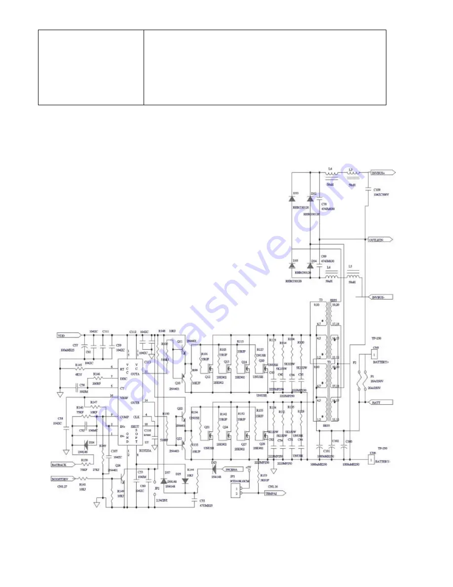
3.Check if the U7 SG3525 is out of order.
4.Check if the Booster Transformer T2
、
T3 is open.
5.After replace the defective devices. To make sure the other parts of the
UPS is OK. Disconnect the logic board from driver board.
Cut off the Utility. Provide 96Vdc to CN5(+) and CN6(-) by a DC
Power Supply, connect CN4 to the main switch. Push on the main
switch and to see if DC POWER of UPS, i.e. VDD(18-16V),
VCC(12V) and +/-5V is normal.
6.5 No LEDs and No Output
FIG. 6.5
Содержание 3 MS series
Страница 7: ...7 1 2 3 4 5 6 7 8 9 Pin 6 RS232 Rx Pin 9 RS232 Tx Pin 7 Ground...
Страница 24: ...24 5 2 Fault LED Lights up and No Output FIG 5 2...
Страница 32: ...32 6 2 Fault LED Lights up and No Output FIG 6 2...
Страница 39: ...39 Appendix a 1 Wiring Diagram a 1 1 For MS 1K...
Страница 41: ...41 a 1 3 For MS3K...
Страница 42: ...42 a 2 Placements a 2 1 For MS1K 220V...
Страница 43: ...43 a 2 2 For MS2K 220V a 2 3 For MS3K...
Страница 44: ...44 a 2 3 For MS3K 220V...
Страница 45: ...45 a 2 4 For MS1K 120V...
Страница 46: ...46 a 2 5 For MS2K 120V...
Страница 47: ...47 a 2 6For MS3K 120V file smenu_ms doc...


