background image

Installing the Audio Drivers for the Windows

®

 NT 4.0 Server / Workstation 

E-1

User's Manual

Appendix E

Installing the Audio Drivers for
the Windows

®

 NT

In this section we will show you how to install the audio drives to your Windows

®

 NT 4.0

Server/Workstation operating system. All screen shot are from Windows

®

 NT 4.0 server

version. Before you install the audio drivers, please install Windows

®

 NT 4.0 Service Pack 4

(or the latest version) first. Then you can install the audio drivers.

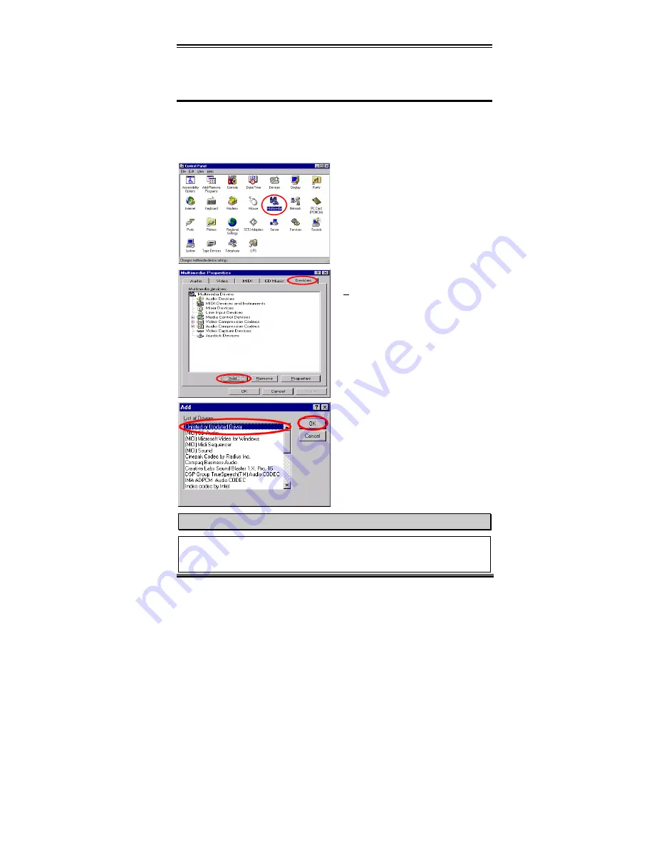
First you need go to the "Control Panel" and

double click the item "Multimedia".

Choose the "Devices" folder then click the

"Add…" button.

Then choose the "Unlisted or Updated

Driver" and click the "OK" button.

NOTE

If you want to play a MIDI file in Windows NT, you have to install Soft Synthesizer S-

YXG50. You can find this software in the WB6 CD-ROM.

Содержание WB6

Страница 1: ...ncidental or consequential damages arising from any defect or error in this manual or product Product names appearing in this manual are for identification purpose only and trademarks and product name...

Страница 2: ......

Страница 3: ...eleron CPU 2 3 2 3 Installing System Memory 2 4 2 4 Connectors Headers and Switches 2 6 Chapter 3 Introduction of The BIOS 3 1 3 1 CPU Soft Menu II 3 4 3 2 Standard CMOS Features Setup Menu 3 9 3 3 Ad...

Страница 4: ...vers for the Windows NT 4 0 Server Workstation Appendix E Installing the Audio Drivers for the Windows NT 4 0 Server Workstation Appendix F BIOS Flashing User Instructions Appendix G Installing the Hi...

Страница 5: ...environment You can connect either Ultra ATA 33 IDE devices or Ultra ATA 66 IDE devices to the IDE connectors on this motherboard The motherboard has built in hardware monitoring functions that can m...

Страница 6: ...ication that defines a hardware scalable Original Equipment Manufacturer OEM motherboard riser board and interface which supports both audio and modem functions The specification s main objective is t...

Страница 7: ...31 May 1995 complies with all known Y2K issues however it may still fail the 2000 exe test Award has modified its BIOS source code to accommodate the requirements of 2000 exe Award BIOS source code is...

Страница 8: ...ernal TV encoder Integrated 24 bit 230MHz RAMDAC DDC2B compliant Motion video acceleration 5 System BIOS CPU SOFT MENU II can easily set the processor parameters AWARD BIOS Supports Plug and Play PnP...

Страница 9: ...t to Line Out Internal 20dB amplifier circuitry for microphone Analog Outputs Stereo LINE Output with volume control True LINE Level with volume control Monaural Output with volume control Supports 3D...

Страница 10: ...Up on LAN Keyboard or Mouse but your ATX power supply 5V standby power must be able to provide at least a 720mA current capacity Otherwise the functions may not work normally Above 66 100 133MHz bus s...

Страница 11: ...Introduction of WB6 Features 1 7 User s Manual 1 3 Layout Diagram Figure 1 3 Motherboard component location...

Страница 12: ...1 8 Chapter1 WB6 1 4 The System Block Diagram Figure 1 4 System diagram of the WB6 mainboard...

Страница 13: ...talling the Motherboard to the Chassis 2 2 Installing the Pentium II II and Celeron processor 2 3 Installing System Memory 2 4 Connectors Headers and Switches Before Proceeding with the Installation B...

Страница 14: ...unable to do this should you attach the board with spacers Take a careful look at the motherboard and you will see many mounting holes on it Line these holes up with the mounting holes on the base If...

Страница 15: ...s on the PCB that are near the fixing hole otherwise it may damage the board or cause board malfunctioning 2 2 Installing the Pentium II III Celeron CPU The installation method for the CPU is printed...

Страница 16: ...2 1 Valid Memory Configurations Bank Memory Module Total Memory Bank 0 1 DIMM1 8MB 16MB 32MB 64MB 128MB 256MB 8MB 256MB Bank 2 3 DIMM2 8MB 16MB 32MB 64MB 128MB 256MB 8MB 256MB Total System Memory 8MB...

Страница 17: ...refer to figure 2 6 for the details This insures the DIMM module will be plugged into the socket in one way only Firmly press the DIMM module into the DIMM socket making certain the module is complet...

Страница 18: ...ase pay attention and read the whole section for necessary information before attempting to finish all of the hardware installation inside the computer chassis Figure 2 7 shows you all of the connecto...

Страница 19: ...h the ATXPWR1 connector insuring that you have a good connection Note Watch the pin position and the orientation CPUFAN and CHAFAN Headers Attach the connector from the individual CPU fan to the heade...

Страница 20: ...m the internal modem adapter to this header This feature lets you wake up your computer via remote control through the modem Note Watch the pin position and the orientation WOL1 Wake on LAN Header If...

Страница 21: ...agement Bus Connector This connector is reserved for system management bus SMBus The SMBus is a specific implementation of an I2 C bus I2 C is a multi master bus which means that multiple chips can be...

Страница 22: ...monitor Of course your TV monitor must have the S Video input jack for a S Video cable connection This card supports both PAL and NTSC systems for various purposes JP 2 3 5 6 8 These jumper settings...

Страница 23: ...le onboard CODEC use AMR CCMOS1 CMOS Discharge Jumper Jumper CCMOS1 discharges the CMOS memory When you install the motherboard make sure this jumper is set for normal operation pin 1 and 2 shorted Se...

Страница 24: ...e is a specific orientation for pins 1 through 3 Insert the three threaded power LED cable to pins 1 3 and the two threaded keylock cable into pins 4 and 5 Check to make sure the correct pins go to th...

Страница 25: ...BIOS setup this function will not work PN2 Pin 1 2 Hardware Reset Switch Header Attach the cable from the case s front panel Reset switch to this header Press and hold the reset button for at least on...

Страница 26: ...ection PIN 12 No connection PIN 12 No connection PIN 13 Ground PIN 13 No connection PN1 PIN 14 Suspend signal PN2 PIN 14 No connection Let s now look at the I O connectors that the WB6 uses and what t...

Страница 27: ...herboard that is the IDE1 connector on the motherboard Secondary refers to the second connector on the motherboard that is the IDE2 connector on the motherboard Two hard disks can be connected to each...

Страница 28: ...on one end a blue connector on the other end and a gray connector in the middle In addition line 34 on the cable should be notched or cut this may be difficult to see Ultra ATA 66 is backwards compat...

Страница 29: ...y of the plastic This fits into the matching slot on the mating plugs on the motherboard and the drives thus assuring positive mating pin 1 to pin 1 The red line on the cable should be aligned with pi...

Страница 30: ...ard hub digital camera joystick etc to one of each USB connector You must make sure your operating system supports this feature and you may need to install an additional driver for individual devices...

Страница 31: ...e to the stereo audio equipment AUX signal input socket Remember the motherboard does not have a built in amplifier to drive the speaker you have to use a speaker that has a built in amplifier Otherwi...

Страница 32: ...2 20 Chapter2 WB6...

Страница 33: ...oduce errors the computer will crash and sometimes you will even not be able to boot the computer after it has crashed We recommend that you do not change the parameters inside the BIOS unless you are...

Страница 34: ...S Setup main menu in Figure 3 1 you can see several options We will explain these options step by step in the following pages of this chapter but let us first see a short description of the function k...

Страница 35: ...rsor symbol appear on the left side of some items indicating that additional information or options can be select in a Sub Menu for this item Note The item heading in the square outlet represents the...

Страница 36: ...ust be setup according its specifications Figure 3 2 CPU Soft Menu II Screen Shot CPU Name Is Intel Pentium IIIMMX Intel Pentium IIMMX Intel Celeron MMX CPU Operating Speed This option sets the CPU sp...

Страница 37: ...gs for your CPU is not the intention of this explanation These should be used for engineering testing not for normal applications If you use non specification settings for normal operation your system...

Страница 38: ...that if you set the L2 cache speed too fast it will cause the L2 cache to fail If the L2 cache fails it will cease to run until you reset the value but the processor and L1 cache will still function...

Страница 39: ...two methods to successfully complete the CPU change operation Method 1 Setup up the CPU for the lowest speed for its brand Turn the power supply off and change the CPU Then turn the system on again an...

Страница 40: ...ssor is installed the BIOS will automatically detect and provide the range that you can use to make the adjustment Spread Spectrum Two options are available Disabled Enabled The default setting is Dis...

Страница 41: ...tings Figure 3 3 Standard CMOS Setup Screen Shot Date mm dd yy You can set the date in this item month mm date dd and year yy Time hh mm ss You can set the time in this item hour hh minute mm and seco...

Страница 42: ...ormat at the factory so you can probably skip this operation Remember though the primary IDE HDD must have its partition set to active within the FDISK procedure If you are using an old HDD that is al...

Страница 43: ...CYLS Heads and Sectors into a logical address where data is located The Cylinders Heads and Sectors displayed in this menu do not reflect the actual structure of the hard disk they are just reference...

Страница 44: ...nter is 0 the maximum number you can enter is 65536 Sector The minimum segment of track length that can be assigned to stored data Sectors usually are grouped into blocks or logical blocks that functi...

Страница 45: ...lt On You can select which type of error will cause the system to halt Five options are available All Errors No Errors All But Keyboard All But Diskette All But Disk Key You can see your system memory...

Страница 46: ...Disabled the default setting being Disabled When this feature is enabled if there is any attempt from a software or an application to access the boot sector or the partition table the BIOS will warn...

Страница 47: ...nd Disabled When you choose Enabled the specific program can read your processor s serial number When you choose Disabled it will not allow the program to read your processor s serial number The defau...

Страница 48: ...as drive A Boot Up Floppy Seek When the computer boots up the BIOS detects if the system has a FDD or not When this item is enable if the BIOS detects no floppy drive it will display a floppy disk dr...

Страница 49: ...the system will not start SETUP When you choose Setup a password is required only when accessing the BIOS Setup If you have not set a password in the PASSWORD SETTING option this option is not availab...

Страница 50: ...of hard disks or CD ROMs They may need a longer amount of time to initialize and prepare for activation Since the BIOS may not detect those kinds of devices during system booting You can adjust the v...

Страница 51: ...e using your system Figure 3 6 Advanced Chipset Features Setup Screen Shot You can use the arrow keys to move between the items Use and Enter key to change the values When you have finished setting up...

Страница 52: ...d Slow gives more stable performance This item applies only when synchronous DRAM is installed in the system System BIOS Cacheable You can select Enabled or Disabled The default setting is Enabled Whe...

Страница 53: ...You can choose the running speed for local memory but if your memory module does not support the speed you choose it may cause a system boot failure or data loss problem Onboard Display Cache Setting...

Страница 54: ...bled The integrated peripheral controller contains an IDE interface with support for two IDE channels If you choose Disabled it will effect the settings of four items not available For example if you...

Страница 55: ...MA 33 select Auto to enable BIOS support For Ultra DMA 66 devices please refer the requirements mentioned in page 2 18 Default setting Disabled If you encounter a problem in using Ultra DMA devices yo...

Страница 56: ...adapter card to connect the modem signal connectors please set this item to Disabled IDE HDD Block Mode Block mode is also called block transfer multiple commands or multiple sector read write If you...

Страница 57: ...rial Port 1 Six options are available Disabled 3F8 IRQ4 2F8 IRQ3 3E8 IRQ4 2E8 IRQ3 AUTO The default setting is 2F8 IRQ3 Onboard IR Function Three options are available IrDA HPSIR mode ASK IR Amplitude...

Страница 58: ...wo options are available EPP1 7 EPP1 9 The default setting is EPP 1 7 When the mode selected for the parallel port mode is EPP the two EPP version options are available ECP Mode Use DMA Two options ar...

Страница 59: ...choose disable the Midi Port Address then this field is not available Note If you buy the audio adapter and want to replace the use of onboard audio solution you have to disable three items in BIOS Ot...

Страница 60: ...ce These are referred to as Power Management Events If none of these events occur the system enters the power saving mode When one of the controlled events occurs the system immediately returns to nor...

Страница 61: ...ices or add on cards support ACPI or not please contact the device or add on card manufacture for more information If you want to know more about ACPI specifications please go to the address below for...

Страница 62: ...r off mode Modem Sleeping mode or power off mode IR command Sleeping mode USB Sleeping mode PS 2 keyboard Sleeping mode PS 2 mouse Sleeping mode Table 3 6 2 Effect of Pressing the Power Switch If the...

Страница 63: ...vices states are compatible with the current Power Resource states Only devices which solely reference Power Resources which are in the ON state for a given device state can be in that device state In...

Страница 64: ...Min 12 Min 13 Min 14 Min 15 Min The default setting is Disabled Min Saving When these two saving modes are enabled the system is set up for minimum power savings Suspend Mode 1 Hour HDD Power Down 15...

Страница 65: ...ult setting is N A Suspend Mode HDD Power Down These two items will be enable to change setting when item Power Management is set to User Define theses two item will also changes as table 3 6 3 below...

Страница 66: ...ust with at least 720mA capability Power On by Ring Two options are available Enabled and Disabled Default setting is Disabled If you connect an external modem to the onboard serial port the system wi...

Страница 67: ...setting is Disabled If any secondary IDE master slave I O activity occurs it will cause the computer to re count the time elapsed FDD COM LPT Port Two options are available Enabled and Disabled Defaul...

Страница 68: ...urations Setup Screen Shot PnP OS Installed The device resource assigned by PnP OS e g Windows 95 or BIOS Force Update ESCD Two options are available Enabled and Disabled Default setting is Disabled N...

Страница 69: ...ources item will be disabled as the BIOS automatically assigns them But if you have trouble in assigning the interrupt resources automatically you can select Manual to set which IRQ and DMA are assign...

Страница 70: ...nother computer and don t want to re install Windows NT then you can specify the IRQ for the device installed on the new computer to fit the original computer settings This feature is for the operatin...

Страница 71: ...re Warning This item lets you select the temperature at which you want the system to send out a warning message to the PC speakers of when the temperature goes beyond either limit You can select the t...

Страница 72: ...n you press Enter on this item you get a confirmation dialog box with a message similar to Load Fail Safe Defaults Y N N Pressing Y loads the BIOS default values for the most stable minimal performanc...

Страница 73: ...nt unauthorized access Password setting procedure When you choose the Set Password option the following message is displayed Enter Password Type your password When complete press Enter The following m...

Страница 74: ...ave to CMOS and EXIT Y N Y Pressing Y stores the selections made in the menus in CMOS a special section of memory that stays on after you turn your system off The next time you boot your computer the...

Страница 75: ...xit Without Saving Screen Shot Pressing Enter on this item asks for confirmation Quit without saving Y N Y This allows you to exit Setup without storing in CMOS any change The previous selections rema...

Страница 76: ...3 44 Chapter3 WB6...

Страница 77: ...Please insert the WB6 CD Title into your CD ROM drive It should execute the program automatically If not you can go to the CD location and execute the execution file from the main directory of this C...

Страница 78: ...ick the Yes to go on This screen will show you the Readme txt information of this INF installation utility When you have read it all click Next Now you can choose the folder for the destination locati...

Страница 79: ...system INF updating When your computer system restarts will see Windows 98 SE start the updating process and several new hardware devices will be found and updated When restarting Windows 98 SE the C...

Страница 80: ...A 4 Appendix A WB6...

Страница 81: ...system now shows the Standard PCI Graphics Adapter VGA Exit the device manager and insert the WB6 CD Title into your CD ROM drive it should execute the program automatically If not you can go to the...

Страница 82: ...0 Graphic Driver and click on it Go to the next screen Move the cursor to Windows 95 98 and click on it Go to the next screen Now you will see the install shield loading You will now see the welcome s...

Страница 83: ...install the driver We suggest you use the default folder as the destination location When you have made sure of the folder click Next Now the system will install the VGA drivers While doing so the pe...

Страница 84: ...ck System Properties Device Manager Display Adapters You should see the device changed to Intel R 810E Chipset Graphics Driver DC133 After you confirm this change the update process is now fully compl...

Страница 85: ...SE We will show you how to install the audio drivers for Windows 98 SE operating system Please enter Control Panel then check System Properties Device Manager Other Devices Your system should now show...

Страница 86: ...for a better driver than the one your device is using now Recommended and then click Next Select Specify a Location and then type D Drivers YMF752 VXD in the text box D is your CD ROM drive letter Cl...

Страница 87: ...Driver for Windows 98 SE C 3 User s Manual Once Windows has restarted go to System Properties to double check You should find the PCI Multimedia Audio Device has disappeared and Yamaha AC XG audio Co...

Страница 88: ...C 4 Appendix C WB6...

Страница 89: ...tall Windows NT 4 0 Service Pack 4 or the latest version first Then you can install the audio drivers Please insert the WB6 CD Title into your CD ROM drive It should execute the program automatically...

Страница 90: ...ogue box will appear Click the Next button to go on The License screen will appear next Click the Yes button to continue Now you can choose the folder for the destination location you want We suggest...

Страница 91: ...s Manual The system will now start to install the VGA drivers While doing so it will display the percentage installed on the screen When installation is complete please choose the item Yes I want to...

Страница 92: ...D 4 Appendix D WB6...

Страница 93: ...T 4 0 server version Before you install the audio drivers please install Windows NT 4 0 Service Pack 4 or the latest version first Then you can install the audio drivers First you need go to the Contr...

Страница 94: ...r computer system Here it is shown as D When Windows finds the driver you can choose the item YAMAHA AC XG Driver and click OK button Click OK The screen shows the System Setting Change message You ne...

Страница 95: ...flash your BIOS One is to directly type the full line commands that are described in this section The utility will then flash your BIOS When you finish the flash operation you will see the screen as...

Страница 96: ...er V7 33 Complete Screen Figure F 3 shows you what commands you can use for the flashing program You need to go into the pure DOS environment and type awdflash Figure F 3 will then appear Figure F 3 A...

Страница 97: ...SY Example 2 To update the BIOS create a backup of current system BIOS and clear the CMOS execute this command AWDFLASH NEWBIOS SAVEBIOS CC Example 3 To update the BIOS and clear PnP settings execute...

Страница 98: ...e content of the disk should be as follows 1 Startup system files COMMAND COM MSDOS SYS IO SYS 2 AWDFLSH EXE 3 The NEWBIOS file which can be download from ABIT web site 4 AUTOEXEC BAT which has the fo...

Страница 99: ...is growing fast but its performance is still unacceptable compared to today s hard drives The transfer rates of today s hard drives can exceed 18MB sec with access times below 12ms However transfer r...

Страница 100: ...should be gone 4 De Installation To uninstall XStore Pro from your system run Uninstall from the HighPoint XStore Pro program group This uninstall utility will deactivate CD Xpress if CD Xpress is ac...

Страница 101: ...he computer The main menu will show up Click the HighPoint XStore Pro Install button and you will see the XStore Pro installer preparing the InstallShield Wizard When it is done the Welcome screen wil...

Страница 102: ...e license screen Step 4 Press Yes to continue Step 5 When the installation process is done you will see the screen below This screen will show up only when you install both XStore Pro and CD Xpress If...

Страница 103: ...hoose the Yes I want to restart my computer now Button Then system will restart Or you can choose the No I will restart my computer later Note You must restart your computer after installing the XStor...

Страница 104: ...G 6 Appendix G WB6...

Страница 105: ...ult in permanent damage to the PC Once any item is out of its normal range a warning message will pop up and remind the user to take the proper measures The following description will tell you how to...

Страница 106: ...o use the default path click the icon to continue the install process Now the screen will show you the percentage of installation progress Step 4 When the process is finished click the OK button Step...

Страница 107: ...u can ignore the warning message of the item but it will pop up again when an error of the same item reoccurs Disable The chosen item will be no longer monitored thereafter unless you activate it in t...

Страница 108: ...in the proper range Secondly after you finished the configuration you have to save it Otherwise the program will start with the default value the next time If you encounter any problems or have any qu...

Страница 109: ...orry about using power to run all the electronics fans and disks When needed a PC with STR function can restore all applications and features to an operational state within a few seconds The following...

Страница 110: ...for the STR function setting How to use the STR function There are two ways to put your system into STR mode Method 1 Select Stand by in the Shut Down Windows area Step 1 Click Star in the Windows Too...

Страница 111: ...Step 1 Open Control Panel and then enter Power Management Step 2 Select Advanced and then set the Power Buttons to Standby Step 3 Restart your computer to put these settings into effect Now you will...

Страница 112: ...I 4 Appendix I WB6...

Страница 113: ...board model BIOS identification number CPU on the technical support form refer to main instructions and describe the problem in the problem description space provided 1 1 1 1 If you can boot up Reinse...

Страница 114: ...s due to the Sound Card Driver Note down the Sound Card model motherboard model BIOS identification number on the technical support file refer to main instructions and describe the problem in the spac...

Страница 115: ...Troubleshooting Need Assistance J 3 User s Manual 4 DRIVER REV Note the driver version number indicated on the DEVICE DRIVER disk if have as Release For example...

Страница 116: ...d and specifications of your CD ROM drive Specify if it uses 4 IDE1 or 4IDE2 and check 5 in case you give no indication we will consider that your CD ROM is 6IDE2 Master Example In the CD ROM drive sp...

Страница 117: ...Technical Support Form Company name 7 Phone 2 Contact 8Fax Model BIOS ID Motherboard Model No DRIVER REV OS Application Hardware name Brand Specifications CPU HDD IDE1 IDE2 CD ROM Drive IDE1 IDE2 Sys...

Страница 118: ...J 6 Appendix J WB6...

Отзывы: