Installing the Motherboard
User’s Manual
3-13
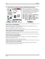
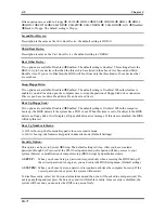
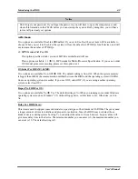
Table 3-2. PANEL1 pin count name and function list
Pin Signal
Name
Function
1
HD_LED_P Hard
disk
LED
pull up (330 ohm) to +5V
2
FP PWR/SLP
MSG LED pull up (330 ohm) to +5V
3
HD_LED_N
Hard disk active LED
4
GND Ground
5
RST_SW_N
Reset Switch low reference pull down (100
ohm) to GND
6
PWR_SW_P
Power Switch high reference pull up (10000
ohm) to +5V
7
RST_SW_P Reset
Switch
high reference pull up (1000
ohm) to +5V
8
PWR_SW_N
Power Switch high reference pull down (100
ohm) to GND
9
RSVD
Reserved (do not use)
10
No Pin
No pin
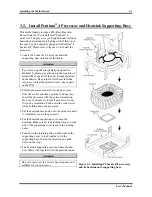
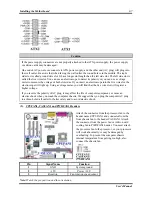
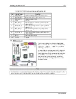
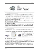
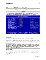
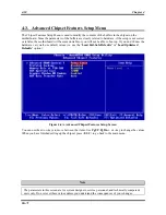
(12). FDD1 Connector
This 34-pin connector is called the “
floppy disk
drive connector
”. You can connect a 360K, 5.25”,
1.2M, 5.25”, 720K, 3.5’’, 1.44M, 3.5” or 2.88M,
3.5” floppy disk drive.
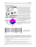
A floppy disk drive ribbon cable has 34 wires and
two connectors to provide the connection of two
floppy disk drives. After connecting the single end
to the FDD1, connect the two connectors on the
other end to the floppy disk drives. In general,
people only install one floppy disk drive on their
computer system.
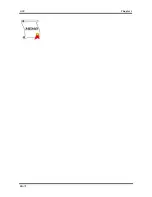
Note
A red mark on a wire typically designates the location of pin 1. You need to align the wire pin 1 to the
FDD1 connector pin 1, and then insert the wire connector into the FDD1 connector.
Содержание SG-71
Страница 2: ......
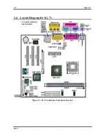
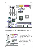
Страница 32: ...Chapter 2 SG 71 2 4 2 4 Layout Diagram for SG 71 Figure 2 1 SG 71 motherboard component location ...
Страница 50: ...Chapter 3 SG 71 3 18 ...
Страница 84: ...Appendix A SG 71 A 4 ...
Страница 88: ...Appendix B SG 71 B 4 ...
Страница 92: ...Appendix C SG 71 C 4 ...
Страница 110: ...Appendix H SG 71 H 6 ...
Страница 114: ...Appendix I SG 71 I 4 ...


