


Installing the Motherboard
User’s Manual
2-15
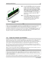
Figure 2-8. Ultra DMA 66
Ribbon Cable Outline
Note
!
The Master or Slave status of the hard disk drive is set on the hard disk itself. Please refer to the
hard disk drive user’s manual.
!
To connect Ultra DMA 100 & Ultra DMA 133 devices on IDE1 to IDE4, an Ultra DMA 66 cable
is required.
!
A red mark on a wire typically designates the location of pin 1. You need to align the wire pin 1 to
the IDE connector pin 1, before inserting the wire connector into the IDE connector.
(12). D14, D16 and D17 LEDs Indicator: Status LEDs indicators
There are three indicators on the motherboard.
D14 is a standby power indicator. When the +5VSB
supplies power to the motherboard, this LED
indicator will light up.
D16 is a power on indicator. When the power button
is pressed, this LED indicator will light up.
D17 is a reset indicator. When you press the reset
button, this LED indicator will light up. If you
release the reset button, this indicator will turn off.
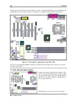
Figure 2-9. KX7-333/KX7-333R back panel connectors
Figure 2-9 shows the KX7-333/KX7-333R back panel connectors, these connectors are for connection to
outside devices to the motherboard. We will describe which devices will attach to these connectors below.
Содержание KX7-333
Страница 2: ......
Страница 26: ...Chapter 2 KX7 333 KX7 333R 2 18 ...
Страница 68: ...4 6 Chapter 4 KX7 333 KX7 333R ...
Страница 76: ...6 4 Chapter 6 KX7 333 KX7 333R ...
Страница 82: ...A 6 Appendix A KX7 333 KX7 333R ...
Страница 88: ...B 6 Appendix B KX7 333 KX7 333R ...
Страница 96: ...D 4 Appendix D KX7 333 KX7 333R Note Items between the are absolutely necessary ...
Страница 100: ...D 8 Appendix D KX7 333 KX7 333R ...
Страница 104: ...E 4 Appendix E KX7 333 KX7 333R ...