


Appendix A
A-4
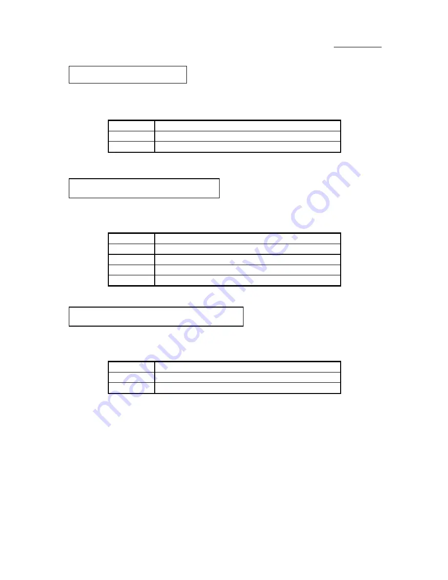
J6 - There is no specific orientation for pins 1
and 2. Insert the two-threads hardware reset connector into the correct pins of
connector on the mainboard.
Pin number
Name of the signal or signification
1
Ground
2
Hardware Reset Signal
J6 - There is no specific orientation
for pin 11 to pin 14. Connect the four-threads speaker cable to the correct pins
of connector on the mainboard
.
Pin number
Name of the signal or signification
11
+5VDC
12
Ground
13
Ground
14
Sound Signal
J6 - There is not specific
orientation for pins 8 and 9. Connect the two-threads connector to the correct
pins of connector on the mainboard.
Pin number
Name of the signal or signification
9
Anode terminal of Turbo LED
8
Cathode terminal of Turbo LED
H/W Reset connector:
Installing speaker connector:
Installing Turbo LED connector:
Содержание AB-AR5
Страница 2: ...Appendix F Technical Support ...
Страница 6: ...1 4 Chapter 1 Layout diagram Fig 1 1 Layout diagram ...
Страница 8: ...1 6 Chapter 1 ...
Страница 28: ...2 20 Chapter 2 ...
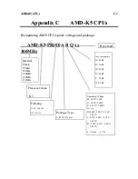
Страница 74: ...Appendix C C 2 ...
Страница 76: ...Appendix D D 2 ...


