background image


EN - 22

BAL.0388.0 • 2018-08-08

11 Disassembly

e

BOX

11 Disassembly

1

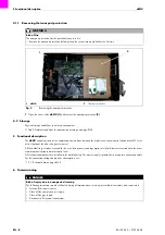
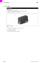
Disconnect the cable assembly from the wire feeder.

2

Disconnect the connection leads from the 

eBOX

.

12 Disposal

When disposing of the system, local regulations, laws, provisions, standards and guidelines must be observed. To correctly 
dispose of the product, it must first be disassembled.

Please note the following information:

11 Disassembly on page EN-22

12.1 Materials

This product is mainly made of metallic materials, which can be melted in steel and iron works and are thus almost infinitely 
recyclable. The plastic materials used are labeled in preparation for their sorting and separation for later recycling.

12.2 Consumables

Oil, greases and cleaning agents may not contaminate the ground or enter the sewage system. These substances must be 
stored, transported and disposed of in suitable containers. Observe the relevant local regulations and disposal instructions 
in the safety data sheets specified by the manufacturer of the consumables. Contaminated cleaning tools (brushes, rags, etc.) 
must also be disposed of in accordance with the information provided by the consumables’ manufacturer. 

12.3 Packaging

ABICOR BINZEL

 has reduced the transport packaging to the necessary minimum. The ability to recycle packaging 

materials is always considered during their selection.

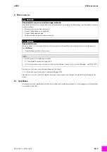
DANGER

Risk of injury due to unexpected start-up

The following instructions must be followed during all maintenance, servicing, assembly, disassembly, and repair work:
• Switch off the power source.
• Close off the compressed air supply.
• Close off the gas supply.
• Switch off the entire welding system.
• Disconnect all electrical connections.

NOTICE

• Disassembly may be carried out only by qualified personnel (in Germany see TRBS 1203).
• Observe also the operating instructions of the welding components, such as the

 welding components,

 welding torch 

system, re-circulating cooling unit etc.

• Observe the information provided in the following section:

8 Decommissioning on page EN-19.

Содержание eBOX MFS-V3

Страница 1: ...C H N O L O G Y F O R T H E W E L D E R S W O R L D www binzel abicor com DE Betriebsanleitung EN Operating instructions FR Mode d emploi ES Instructivo de servicio MFS V3 DE eBOX EN eBOX FR eBOX ES e...

Страница 2: ...E 3 2 4 Klassifizierung der Warnhinweise DE 4 2 5 Angaben f r den Notfall DE 4 3 Produktbeschreibung DE 4 3 1 Technische Daten DE 5 3 2 Abk rzungen DE 5 3 3 Typenschild DE 6 3 4 Verwendete Zeichen und...

Страница 3: ...dabei die Betriebs Wartungs und lnstandhaltungsbedingungen Jede andere Verwendung gilt als nicht bestimmungsgem Eigenm chtige Umbauten oder Ver nderungen zur Leistungssteigerung sind nicht zul ssig 2...

Страница 4: ...t gemieden wird sind Tod oder schwerste Verletzungen die Folge WARNUNG Bezeichnet eine m glicherweise gef hrliche Situation Wenn sie nicht gemieden wird k nnen schwere Verletzungen die Folge sein VORS...

Страница 5: ...gsbedingungen Transport und Lagerung Gewicht 21 5 kg Anschlussspannung 100 240 V AC 50 oder 60 Hz Betriebsspannung intern 24 VDC 38 VDC Leistungsaufnahme 1 0 kW Schutzart IP21 Tab 3 eBOX 600 685 214 3...

Страница 6: ...Ger tenummer Servicenummer Baujahr Firmware Feldbus System 3 4 Verwendete Zeichen und Symbole In der Betriebsanleitung werden folgende Zeichen und Symbole verwendet Abb 2 Typenschild eBOX Symbol Besch...

Страница 7: ...sskabel Kundenspezifisch SD Karte mit eBOX Backup Dateien Kundenspezifisch Betriebsanleitung Tab 5 Lieferumfang Handterminal MF Control Tab 6 Optionen Eingangskontrolle Kontrollieren Sie die Vollst nd...

Страница 8: ...den ber mikroprozessorgesteuerte Motorregeleinheiten an die Antriebe weitergegeben Alle Elektronikbauteile sind im Metallgeh use installiert Die Stromversorgung wird ber ein separates Anschlusskabel h...

Страница 9: ...Netzteil versorgt 6 2 1 Versorgung intern In diesem Fall m ssen folgende Jumpereinstellungen auf der Hauptplatine 4 vorgenommen werden 1 Jumpereinstellungen 1 on untere Position 2 on linke Position 3...

Страница 10: ...vermeiden In diesem Fall m ssen folgende Jumpereinstellungen auf der Hauptplatine 4 vorgenommen werden Halten Sie bei externer Versorgung folgende Reihenfolge ein 1 Jumpereinstellungen 1 off obere Pos...

Страница 11: ...3 Anschl sse herstellen 6 3 1 eBOX M Drive Standard MasterLiner Anschl sse gem folgender Abbildung vornehmen 1 M Drive 2 Anschluss Steuerleitung X11 3 eBOX 4 Steuerleitung 5 Anschluss Steuerleitung X4...

Страница 12: ...eBOX 6 3 2 eBOX MF1 Anschl sse gem folgender Abbildung vornehmen 1 Drahtendesensor 2 Fass 3 eBOX 4 Steuerleitung eBOX Masterantrieb 5 Masterantrieb MF1 6 Flexzuf hrung 7 MasterLiner 8 Steuerleitung Dr...

Страница 13: ...MF1 Rear Anschl sse gem folgender Abbildung vornehmen 1 Drahtendesensor 2 Fass 3 eBOX 4 Steuerleitung Drahtendesensor 5 Steuerleitung eBOX MF1 MF1DIG Sensor 6 Flexzuf hrung 7 MF1 8 MasterLiner 9 MF1...

Страница 14: ...3 3 Typenschild auf Seite DE 6 1 Netzstecker in Netzanschluss X1 1 einstecken GEFAHR Stromschlag Gef hrliche Spannung durch fehlerhafte Kabel berpr fen Sie alle spannungsf hrenden Kabel und Verbindun...

Страница 15: ...boter X2 2 Handterminal Option X10 3 M Drive eBOX X1 1 Abb 10 Steckerbelegung bersicht 3 2 1 X1 Pin Beschreibung Signals 1 L1 2 3 4 N 5 PE PE Tab 8 Anschluss Netzkabel X2 Pin Beschreibung Signals 1 24...

Страница 16: ...rtgeber Ch A B4 Istwertgeber Ch B B5 Front Drive B6 Front Drive B7 Rear Drive B8 Rear Drive B9 Klemmleiste 24V f r Inching Init Reverse B10 Reset Geschaltet zur ck C1 Inching Gechaltet zur ck C2 Gesch...

Страница 17: ...4VDC 2 GND 3 CAN A 4 CAN B 5 GND 6 7 8 Schirm PE Tab 11 Anschluss Handterminal Option X3 Pin Beschreibung Signals 1 US1 24VDC 2 US1 GND 3 US2 24VDC 4 US2 GND 5 PE Tab 12 Anschluss US1 US2 nur bei AIDA...

Страница 18: ...15 16 17 13 12 Symbol Bezeichnung Hauptschalter Q1 16 Abb 11 Schaltzustand EIN LEDs leuchten gr n Ger tel fter laufen Schaltzustand AUS System ist stromlos Schl sselschalter S1 2 Abb 11 Schaltzustand...

Страница 19: ...von Wartungs Instandhaltungs Montage bzw Demontage und Reparaturarbeiten ist Folgendes zu beachten Schalten Sie die Stromquelle aus Sperren Sie die Druckluftzufuhr ab Sperren Sie die Gaszufuhr ab Tre...

Страница 20: ...ngsintervalle sind Richtwerte und beziehen sich auf den Einschichtbetrieb 1 Luftgitter Geh usezuluft 2 Luftgitter Geh useabluft Abb 12 Steckerbelegung bersicht W chentlich Monatlich Viertelj hrlich Lu...

Страница 21: ...n der schwei technischen Komponenten wie z B Stromquelle Schwei brenner System Umlaufk hlaggregat usw St rung Ursache Behebung Ger t ist nicht funktionsbereit Steuerung bzw Bauteil defekt Defekte Steu...

Страница 22: ...n Sie dabei die entsprechenden rtlichen Bestimmungen und die Hinweise zur Entsorgung der vom Betriebsmittelhersteller vorgegebenen Sicherheitsdatenbl tter Kontaminierte Reinigungswerkzeuge Pinsel Lapp...

Страница 23: ...eBOX 13 Optionen BAL 0388 0 2018 08 08 DE 23 13 Optionen 13 1 Handterminal MF Control Beachten Sie die Angaben der entsprechenden Betriebsanleitung...

Страница 24: ...nt PPE EN 3 2 4 Classification of the warnings EN 4 2 5 Emergency information EN 4 3 Product description EN 4 3 1 Technical data EN 5 3 2 Abbreviations EN 5 3 3 Nameplate EN 6 3 4 Signs and symbols us...

Страница 25: ...nditions Any other use is considered improper Unauthorized conversions or power increase modifications are not permitted 2 2 Obligations of the operator Keep the operating instructions within easy rea...

Страница 26: ...cription DANGER Describes an imminent threatening danger If not avoided this will result in fatal or extremely critical injuries WARNING Describes a potentially dangerous situation If not avoided this...

Страница 27: ...bient conditions for transport and storage Weight 21 5 kg Connection voltage 100 240 V AC 50 or 60 Hz Internal operating voltage 24 VDC 38 VDC Power consumption 1 0 kW Protection type IP21 Tab 3 eBOX...

Страница 28: ...vice type Device number Service number Year of construction Firmware Field bus system 3 4 Signs and symbols used The following signs and symbols are used in the operating instructions Fig 2 eBOX namep...

Страница 29: ...terface customer specific Mains cable customer specific SD card with eBOX backup files customer specific Operating instructions Tab 5 Scope of delivery Manual terminal for the MF Control Tab 6 Options...

Страница 30: ...es via microprocessor based motor control units All electronic components are installed in the metal housing The power supply is provided via a separate connecting cable For the connection voltage and...

Страница 31: ...owered by an internal power supply unit by default 6 2 1 Internal power supply When using an internal power supply configure the following jumper settings on the main PCB 4 1 Set jumper 1 to on bottom...

Страница 32: ...upply fails When using an external power supply configure the following jumper settings on the main PCB 4 always retaining the order shown 1 Set jumper 1 to off top position jumper 2 to on left positi...

Страница 33: ...lishing connections 6 3 1 eBOX M Drive standard MasterLiner Establish the connections as shown in the following diagram 1 M Drive 2 Port for control lead X11 3 eBOX 4 Control lead 5 Port for control l...

Страница 34: ...3 2 eBOX MF1 Establish the connections as shown in the following diagram 1 Wire end sensor 2 Barrel 3 eBOX 4 Control lead eBOX masterfeeder 5 Masterfeeder MF1 6 Flex suppley 7 MasterLiner 8 Wire end...

Страница 35: ...ar Establish the connections as shown in the following diagram 1 Wire end sensor 2 Barrel 3 eBOX 4 Wire end sensor control lead 5 Control lead eBOX MF1 MF1DIG sensor 6 Flex supply 7 MF1 8 MasterLiner...

Страница 36: ...see 3 1 Technical data on page EN 5 3 3 Nameplate on page EN 6 1 Insert the mains plug into the mains port X1 1 DANGER Electric shock Dangerous voltage due to defective cables Check all live cables a...

Страница 37: ...t X2 2 Manual terminal optional X10 3 M Drive eBOX X11 Fig 10 Overview of the pin assignment 3 2 1 X1 pin Description Signals 1 L1 2 3 4 N 5 PE PE Tab 8 Mains cable port X2 pin Description Signals 1 2...

Страница 38: ...alue encoder Ch A B4 Actual value encoder Ch B B5 Front drive B6 Front drive B7 Rear drive B8 Rear drive B9 Terminal strip 24 V for inching init reverse B10 Reset Switched back C1 Inching Switched bac...

Страница 39: ...GND 3 CAN A 4 CAN B 5 GND 6 7 8 Screen PE Tab 11 Manual terminal port optional X3 pin Description Signals 1 US1 24 VDC 2 US1 GND 3 US2 24 VDC 4 US2 GND 5 PE Tab 12 US1 US2 port on AIDA version only X...

Страница 40: ...0 11 14 15 16 17 13 12 Symbol Name Main switch Q1 16 Fig 11 Switching state ON LEDs illuminated in green device fans running Switching state OFF no power to the system Key operated switch S1 2 Fig 11...

Страница 41: ...Risk of injury due to unexpected start up The following instructions must be followed during all maintenance servicing assembly disassembly and repair work Switch off the power source Close off the c...

Страница 42: ...d refer to single shift operation 1 Air grille housing air inlet 2 Air grille housing air outlet Fig 12 Overview of the pin assignment 1 2 Weekly Monthly Quarterly Check clean and depending on the lev...

Страница 43: ...uctions for the welding components such as the power source welding torch system re circulating cooling unit etc Fault Cause Solution Unit is not ready for operation Control system or component defect...

Страница 44: ...gulations and disposal instructions in the safety data sheets specified by the manufacturer of the consumables Contaminated cleaning tools brushes rags etc must also be disposed of in accordance with...

Страница 45: ...eBOX 13 Options BAL 0388 0 2018 08 08 EN 23 13 Options 13 1 Manual terminal for the MF Control Please see the information in operating instructions...

Страница 46: ...ation des consignes d avertissement FR 4 2 5 Instructions concernant les situations d urgence FR 4 3 Description du produit FR 5 3 1 Caract ristiques techniques FR 5 3 2 Abr viations FR 6 3 3 Plaque s...

Страница 47: ...s d autorit pour augmenter la puissance sont interdites 2 2 Obligations de l exploitant Le mode d emploi doit tre tenu proximit de l appareil pour pouvoir tre consult Si le produit est remis des tiers...

Страница 48: ...tations suivantes Alimentation lectrique D autres mesures sont d crites dans le mode d emploi de la source de courant ou dans la documentation des dispositifs p riph riques suppl mentaires DANGER Sign...

Страница 49: ...puissance sont interdites L appareil ne doit tre utilis que par des personnes autoris es en Allemagne voir TRBS 1203 Fig 1 Dimensions eBOX Temp rature de l air ambiant 10 C 40 C Humidit relative de l...

Страница 50: ...rication Micrologiciel Syst me de bus de terrain MFS V3 Syst me de d vidage complet avec eBOX dot d un ou de deux d vidoirs et quip de tous les m dias et c bles de commande n cessaires MF1 D vidoir c...

Страница 51: ...et devant tre ex cut es dans l ordre eBOX pr t l emploi mod le analogique num rique ou avec interface pour bus de terrain sp cifique au client C ble de raccordement secteur sp cifique au client Carte...

Страница 52: ...ource de courant de fil chaud Toutes les valeurs de consigne n cessaires l avance du fil transmises en mode analogique num rique ou par le biais d un bus de terrain sont transmises aux d vidoirs par l...

Страница 53: ...en cas de d marrage inattendu Pendant toute la dur e des travaux d entretien de maintenance de montage de d montage et de r paration respectez les points suivants Mettez la source de courant hors cir...

Страница 54: ...e 6 2 1 Alimentation interne En l occurrence il est n cessaire d effectuer les ajustements suivants au niveau des cavaliers de la carte m re 4 1 Ajustement des cavaliers 1 position on en bas 2 positio...

Страница 55: ...ence il est n cessaire d effectuer les ajustements suivants au niveau des cavaliers de la carte m re 4 En cas d alimentation ext rieure la s quence d ajustement est la suivante 1 Ajustez le cavalier 1...

Страница 56: ...3 1 eBOX et M Drive standard MasterLiner Proc dez aux raccordements conform ment l illustration suivante 1 M Drive 2 Raccord pour c ble de commande X11 3 eBOX 4 C ble de commande 5 Raccord pour c ble...

Страница 57: ...raccordements conform ment l illustration suivante 1 D tecteur de fin de fil 2 F t 3 eBOX 4 C ble de commande eBOX entra nement ma tre Master Feeder 5 Master Feeder MF1 6 Conduit flexible 7 MasterLine...

Страница 58: ...accordements conform ment l illustration suivante 1 D tecteur de fin de fil 2 F t 3 eBOX 4 C ble de commande du d tecteur de fin de fil 5 C ble de commande eBOX MF1 MF1DIG capteur 6 Conduit flexible 7...

Страница 59: ...FR 5 3 3 Plaque signal tique la page FR 6 1 Branchez la fiche secteur dans le raccord secteur X1 1 DANGER Risque de choc lectrique Tension dangereuse en pr sence de c bles d fectueux Veillez ce que t...

Страница 60: ...al manuel option X10 3 M Drive eBOX X11 Fig 10 Vue d ensemble de l affectation des connecteurs 3 2 1 Broche X1 Description Signaux 1 L1 2 3 4 N 5 PE PE Tab 8 Raccord pour c ble secteur Broche X2 Descr...

Страница 61: ...r des valeurs r elles Canal B B5 Moteur avant B6 Moteur avant B7 Moteur arri re B8 Moteur arri re B9 R glette de bornes 24 V pour Inching Init Reverse enfilage initialisation inversion de sens B10 R i...

Страница 62: ...4 V c c 2 GND 3 CAN A 4 CAN B 5 GND 6 7 8 Blindage PE Tab 11 Raccord pour terminal manuel option Broche X3 Description Signaux 1 US1 24 V c c 2 US1 GND 3 US2 24 V c c 4 US2 GND 5 PE Tab 12 Raccord US1...

Страница 63: ...12 Symbole D signation Interrupteur principal Q1 16 fig 11 tat de commutation MARCHE voyants verts ventilateurs en marche tat de commutation ARR T syst me hors tension Interrupteur cl S1 2 fig 11 tat...

Страница 64: ...d entretien de maintenance de montage de d montage et de r paration respectez les points suivants Mettez la source de courant hors circuit Coupez l alimentation en air comprim Coupez l alimentation e...

Страница 65: ...nement par quipes de 8 h 1 Grille d a ration air entrant dans le bo tier 2 Grille d a ration air sortant du bo tier Fig 12 Vue d ensemble de l affectation des connecteurs Toutes les semaines Tous les...

Страница 66: ...rant le syst me de torche de soudage le groupe refroidisseur etc Probl me Cause Solution Appareil non op rationnel Commande ou composant d fectueux Faites remplacer la commande ou le composant d fectu...

Страница 67: ...qui figurent sur les fiches de donn es de s curit du fabricant des consommables Les outils de nettoyage contamin s pinceaux chiffons etc doivent galement tre limin s selon les indications du fabricant...

Страница 68: ...advertencias ES 4 2 5 Indicaciones para emergencias ES 4 3 Descripci n del producto ES 5 3 1 Datos t cnicos ES 5 3 2 Abreviaturas ES 6 3 3 Placa de identificaci n ES 6 3 4 Signos y s mbolos utilizado...

Страница 69: ...idera como no conforme a lo prescrito Las reformas o modificaciones para el incremento de capacidad realizadas por decisi n propia no est n permitidas 2 2 Responsabilidad del operador del sistema El m...

Страница 70: ...rg a el ctrica Para conocer m s medidas consulte el manual de instrucciones de la fuente de corriente o la documentaci n del resto de aparatos perif ricos PELIGRO Indica un peligro inminente Si no se...

Страница 71: ...e ser utilizado exclusivamente por personal cualificado en Alemania v ase TRBS 1203 Fig 1 Dimensiones de eBOX Temperatura ambiental 10 C hasta 40 C Humedad relativa del aire hasta 90 a 20 C Tab 1 Cond...

Страница 72: ...FS V3 Sistema de devanadora o alimentador completo compuesto por eBOX con uno o dos accionamientos de hilo o alambre y todos los medios y cables de control necesarios MF1 Accionamiento de hilo o alamb...

Страница 73: ...rmaci n detallada complementaria o adicional 1 Pasos de acci n que deben realizarse en ese orden eBOX listo para funcionamiento anal gico digital o con interfaz de bus de campo espec fico de cliente C...

Страница 74: ...ransmiten a los accionamientos por medio de unidades de control de motor controladas por microprocesador Todos los componentes electr nicos est n integrados en la carcasa met lica El suministro de cor...

Страница 75: ...de potencia interna 6 2 1 Alimentaci n interna En este caso se deben realizar los siguientes ajustes de puentes en el circuito integrado principal 4 1 Ajustes de puentes 1 on posici n inferior 2 on p...

Страница 76: ...nsi n interna En este caso se deben realizar los siguientes ajustes de puentes en el circuito integrado principal 4 En la alimentaci n externa siga este orden 1 Ajustes de puentes 1 off posici n super...

Страница 77: ...to de conexi n 6 3 1 eBOX y M Drive est ndar MasterLiner Realice las conexiones seg n la siguiente ilustraci n 1 M Drive 2 Puerto para cable de control X11 3 eBOX 4 Cable de control 5 Puerto para cabl...

Страница 78: ...las conexiones seg n la siguiente ilustraci n 1 Sensor final de hilo 2 Barril 3 eBOX 4 Cable de control de eBOX devanadora o alimentador 5 Devanadora o alimentador MF1 6 Contucto flexible 7 MasterLin...

Страница 79: ...las conexiones seg n la siguiente ilustraci n 1 Sensor final de hilo 2 Barril 3 eBOX 4 Cable de control de sensor final de hilo 5 Cable de control de eBOX MF1 MF1DIG Sensor 6 Contucto flexible 7 MF1...

Страница 80: ...a p gina ES 5 3 3 Placa de identificaci n en la p gina ES 6 1 Inserte el conector de red en la conexi n a la red X1 1 PELIGRO Electrocuci n Tensi n peligrosa por cables defectuosos Compruebe que todos...

Страница 81: ...ando manual opci n X10 3 M Drive eBOX X11 Fig 10 Vista general de la asignaci n de clavijas 3 2 1 Clavija X1 Descripci n Se ales 1 L1 2 3 4 N 5 PE PE Tab 8 Conector para cable de red Clavija X2 Descri...

Страница 82: ...B3 Transmisor de valor real Ch A B4 Transmisor de valor real Ch B B5 Accionamiento delantero B6 Accionamiento delantero B7 Accionamiento trasero B8 Accionamiento trasero B9 Regleta de bornes 24V para...

Страница 83: ...4 CAN B 5 GND 6 7 8 Pantalla PE Tab 11 Conector para elemento de mando manual opci n Clavija X3 Descripci n Se ales 1 US1 24VDC 2 US1 GND 3 US2 24VDC 4 US2 GND 5 PE Tab 12 Puerto US1 US2 solo con vers...

Страница 84: ...entos de control de eBOX 1 2 3 4 5 6 7 8 9 10 11 14 15 16 17 13 12 S mbolo Denominaci n Interruptor principal Q1 16 fig 11 Conectado LED iluminados en verde ventilador en funcionamiento Desconectado s...

Страница 85: ...es por arranque inesperado Lleve a cabo las acciones siguientes durante todos los trabajos de mantenimiento mantenimiento correctivo montaje desmontaje y reparaci n Desconecte la fuente de corriente C...

Страница 86: ...alores orientativos y se refieren al trabajo de un turno 1 Rejilla de entrada de aire en la carcasa 2 Rejilla de salida de aire de la carcasa Fig 12 Vista general de la asignaci n de clavijas Semanal...

Страница 87: ...plo la fuente de corriente el sistema de antorcha de soldadura el recirculador de refrigerante etc Aver a Causa Eliminaci n El equipo no funciona Sistema de control o componente defectuoso Solicitar a...

Страница 88: ...s apropiados Observe para ello las disposiciones locales correspondientes y las indicaciones para la eliminaci n de desechos especificadas en las fichas de datos de seguridad del fabricante Los tiles...

Страница 89: ...eBOX 13 Opciones BAL 0388 0 2018 08 08 ES 23 13 Opciones 13 1 Elemento de mando manual para MF Control Tenga en cuenta las indicaciones del instructivo de servicio...

Страница 90: ...ES 24 BAL 0388 0 2018 08 08 Notizen Notes Notas eBOX Notizen Notes Notas...

Страница 91: ...eBOX Notizen Notes Notas BAL 0388 0 2018 08 08 ES 25 Notizen Notes Notas...

Страница 92: ...R T H E W E L D E R S W O R L D www binzel abicor com Alexander Binzel Schweisstechnik GmbH Co KG Postfach 10 01 53 D 35331 Giessen Tel 49 0 64 08 59 0 Fax 49 0 64 08 59 191 Email info binzel abicor c...

Отзывы: