eBOX
6 Commissioning
BAL.0388.0 • 2018-08-08
EN - 9
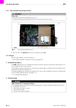
Remove the transport protection before putting the system into operation for the first time.
4.1.1 Removing the transport protection on page EN-8
Install the service software before putting the system into operation for the first time. To do this, please refer to the information
in the service software operating instructions.
6.1 Installation
Select an installation site with sufficient ventilation and clearance for the housing fan.
6.2 eBOX US1 power supply for the bus module and logic circuit
The
eBOX
's logic circuit is powered by an internal power supply unit by default.
6.2.1 Internal power supply
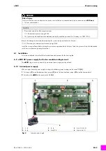
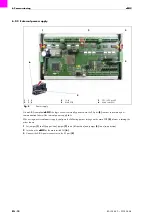
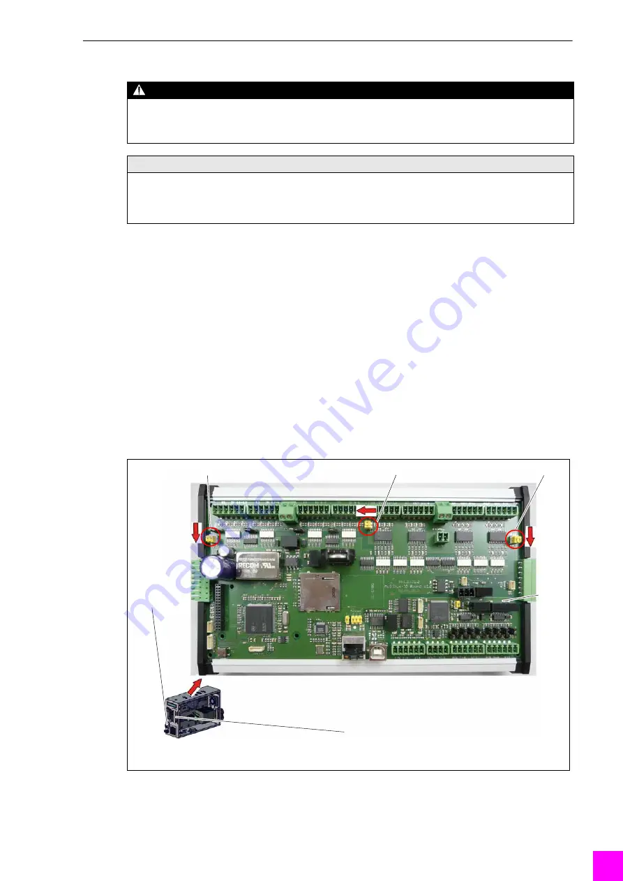
When using an internal power supply, configure the following jumper settings on the main PCB
1
Set jumper
to on (bottom position), jumper
to on (left position) and jumper
to on (bottom position).
2
Switch on the
eBOX
at the main switch Q1
.
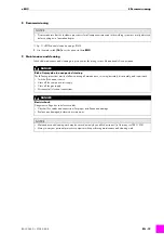
DANGER
Risk of injury
Safety switches on covers and protective devices are ineffective in manual mode (only in connection with
M-Drive
).
• Greater concentration.
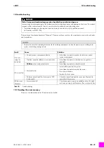
NOTICE
• Please take note of the following instructions:
3 Product description on page EN-4
• The system may be installed and commissioned only by qualified personnel (in Germany, see TRBS 1203).
1
J1, J2
2
J3, J4
3
J5, J6
4
Main PCB
5
Port US1/US2 X3
6
Main switch Q1
Fig. 4
Internal power supply
1
2
3
6
5
4


