T E C H N O L O G Y F O R T H E W E L D E R ´ S W O R L D .
www.binzel-abicor.com
DE
Betriebsanleitung
/ EN
Operating instructions
FR
Mode d'emploi
/ ES
Instructivo de servicio
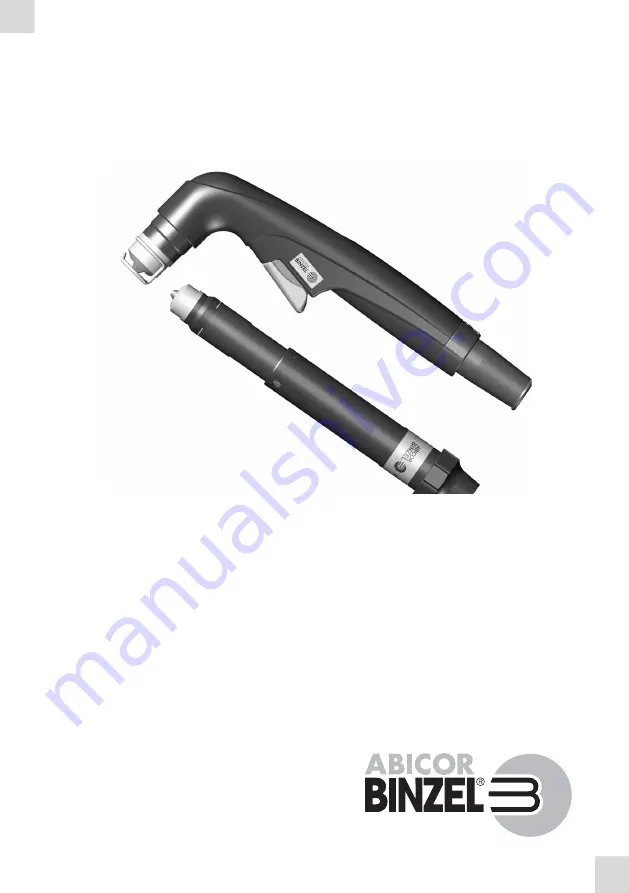
ABIPLAS
®
CUT HF
DE
Plasma-Schneidbrenner
EN
Plasma cutting torches
FR
Torches de coupage plasma
ES
Antorchas de corte por plasma


