background image

8

AirCleaner

  •  

User Guide

2. Installation

Panic Button Control Panel Mounting

Panic Button Control Panel Mounting

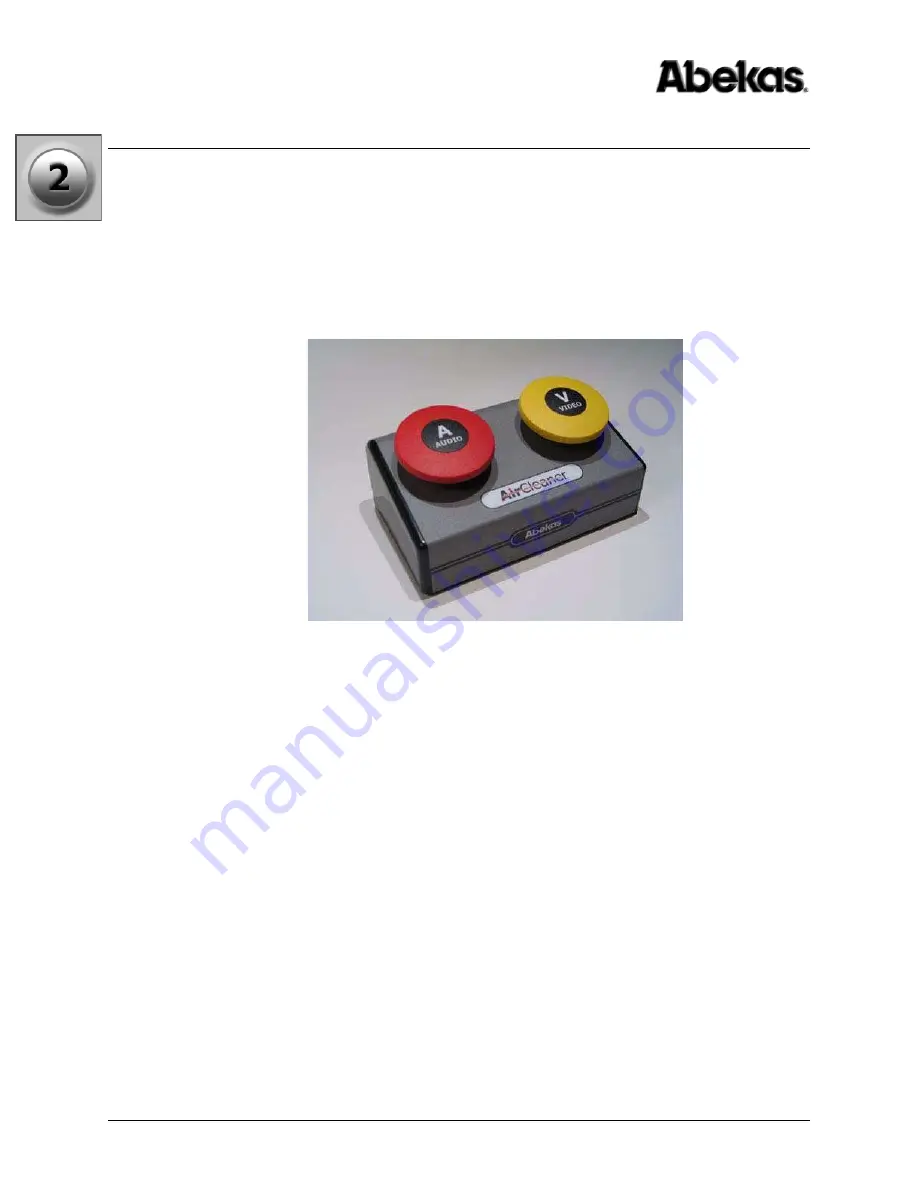
The Panic Button Control Panel option is designed to sit on a console or table top, and 
has no special mounting or cooling instructions. The dimensions of the panel include 
the rubber feet on the underside of the Panic Button Control Panel.

One or two Control Panels can be attached to a single AirCleaner chassis.

Dimensions: 6.25” W x 4.10” D x 3.10” H

Metric Dimensions: 15.87cm W x 10.4cm D x 7.87cm H

Figure 2-4.  Panic Button Control Panel

Содержание AirCleaner

Страница 1: ... 1 45W Software Table of Contents vii Chapter 1 Introduction 1 Chapter 2 Installation 5 Chapter 3 Maintenance 23 Chapter 4 Operations 45 Menu Flow Charts 91 Index 93 Go directly to any chapter by clicking on the link in the list above ...

Страница 2: ...ii AirCleaner User Guide ...

Страница 3: ...2006 Published in the United States of America Notice The information in this guide is subject to change without notice or obligation and does not represent a commitment on the part of Abekas Incorporated Acknowledgments Registered product trademarks or names used in this manual are the exclusive property of that equipment or software manufacturer Their usage in this manual is with beneficial inte...

Страница 4: ...ions to this product not authorized by Abekas Incorporated could void the FCC Compliance and negate authority to operate the product This product was tested for FCC compliance under conditions that included the use of Abekas peripheral devices and Abekas shielded cables and connectors between system components It is important that Abekas peripheral devices are used and shielded cables and connecto...

Страница 5: ...ion of the proper international plug supplied by the customer To ensure safe operation and to guard against potential shock or risk of fire ensure the power source is within the required voltage range and frequency for which the AirCleaner power supply has been set Input AC Power Requirement 100 to 240VAC 3 to 1 5A 60 to 50Hz WARNING AirCleaner uses open module power supplies with UNUSUALLY HIGH C...

Страница 6: ...ner optimum operating environment is within the following ranges Recommended Operating Temperature 20 C to 35 C 68 F to 95 F Recommended Operating Humidity 20 to 80 non condensing Safety Information NOTE High temperature humidity should be avoided at all times ...

Страница 7: ...dundant Power Supply 3 Panic Button Control Panel 4 Panic Button Y Cable 4 Chapter 2 Installation 5 In This Chapter 5 Unpacking 5 Cooling and Airflow 6 Power Consumption 6 Chassis Dimensions 7 Chassis Rack Mounting 7 Panic Button Control Panel Mounting 8 Video Connections 9 PGM IN Video 9 PGM OUT Video 9 AUX IN Video 10 TAP OUT Video 10 REF IN 10 Audio Connections 11 STEREO ANALOG AUDIO OUTPUT 11 ...

Страница 8: ...ogramming41 Chapter 4 Operations 45 In This Chapter 45 Overview 45 Theory of Operation 46 Front Panel 54 BYPASS Button 54 Menu Control Panel 55 Delay Times 55 Reaction Time 56 The AutoClean Feature 56 Determining Operator Reaction Time 56 One Screener Reaction Time Example 57 Two Screener Reaction Time Example 58 Drawback of Very Large Reaction Time 59 User Configurations 61 Mode 1 One Screener Sw...

Страница 9: ... Panel 69 Navigating to the Main Menu 69 Navigate to Main Menu from Options Menu 69 Navigate to Main Menu from User Memory Menu 70 Navigating to Options and User Memory Menus 70 Navigate to the Options Menu 70 SAVE CHANGES made in the Options Menu 70 Navigate to the User Memory Menu 71 Control Panel Menu Item Descriptions 72 Main Menu Parameters 72 User Memory Menu Parameters 82 Loading a User Mem...

Страница 10: ...x AirCleaner User Guide Table of Contents ...

Страница 11: ...also provides full operational information and descriptions for all menu settings in the AirCleaner user interface The following chapters provide instructions for all aspects of AirCleaner This chapter Introduction on page 1 describes how to use this User Guide and provides a complete system overview Chapter 2 Installation on page 5 provides details on AirCleaner power cooling and airflow site pre...

Страница 12: ...hin the current file As required use Acrobat s On Line Help file to familiarize yourself with all of Acrobat s navigational features Acrobat provides incredible search capabilities Use the Find tool to search for words in the currently open file or use the Search Index tool to perform a complete search of all chapter files Please use Acrobat s On Line Help file to learn more about search functiona...

Страница 13: ... popular video formats supported It s equipped with two SD HD SDI video inputs two SD HD SDI video outputs and has an analog reference input AirCleaner handles eight channels 4 stereo pairs of AES EBU audio for each of the two video I O streams AirCleaner can also utilized digital audio that s embedded in the digital video I O streams AirCleaner also features a single stereo analog audio monitorin...

Страница 14: ...own Panic Button Control Panel to fit their workflow however Abekas provides this option for those customers who don t wish to build their own control panels The Panic Button Control Panel ships with a 33 foot shielded cable for connection to the GPI connector on the AirCleaner main chassis Panic Button Y Cable In some instances AirCleaner can be operated in a two screener mode which requires a se...

Страница 15: ...Connection 13 Unpacking Remove the AirCleaner main chassis and Panic Button Control Panel optional from the packing boxes Also remove the rack rails and any cables or other packaging that may be included Inspect all articles for shipping damage If any damage is found please notify the shipping carrier immediately for claims adjustments Compare the shipping box contents to the packing slip Contact ...

Страница 16: ...nsumes a maximum of 300 watts average operating power is about 60 watts An optional redundant power supply is available when it s installed and in operation the main and redundant power supplies will share the power load equally and will therefore not change the overall power consumption There is no AC power connection to the Panic Button Control Panel WARNING AirCleaner uses open module power sup...

Страница 17: ...aner comes with rack ears for the front and rack rails for mounting the rear of the chassis into a rack All necessary hardware for mounting these pieces to the AirCleaner chassis is included Rack screws are not included With the rack ears in place the total chassis width is 19 0 inches 48 26 cm The chassis is 1RU in height 1 75 26 67cm Figure 2 3 Chassis Rack Mountings 1 75 in 4 45 cm 17 0 in 43 1...

Страница 18: ... console or table top and has no special mounting or cooling instructions The dimensions of the panel include the rubber feet on the underside of the Panic Button Control Panel One or two Control Panels can be attached to a single AirCleaner chassis Dimensions 6 25 W x 4 10 D x 3 10 H Metric Dimensions 15 87cm W x 10 4cm D x 7 87cm H Figure 2 4 Panic Button Control Panel ...

Страница 19: ...s digital video input can be either Standard Definition SMPTE 259M EBU Tech 3267 E or High Definition SMPTE 292M The programmed video format of this video input will always follow the configuration of the video output This digital video input can carry up to eight tracks four stereo pair of embedded digital audio PGM OUT Video Delayed Video Output This is the delayed Live to Air serial digital vid...

Страница 20: ...r s video delay pathway This digital video output can be either Standard Definition SMPTE 259M EBU Tech 3267 E or High Definition SMPTE 292M The video format and line standard for this output is configured in the Option Menu this selection will be the same for all the video inputs and outputs This digital video output can carry eight tracks of embedded digital audio REF IN Reference Input This inp...

Страница 21: ...ons are provided on female BNC AirCleaner also has one analog stereo output provided on a 3 5mm jack STEREO ANALOG AUDIO OUTPUT This 3 5mm female stereo jack provides monitoring of analog audio output In the AirCleaner user interface a selection can be made to monitor any stereo pair from the PGM OUT audio output The output level is 0dBmV The Analog Audio OUT parameter in the Main Menu controls th...

Страница 22: ...er is programmed to switch to the auxiliary input during an AUDIO Panic Button press this is the Safe digital audio input into AirCleaner that is used for the safe feed If AirCleaner is programmed to mute the audio during an AUDIO Panic Button press then this input is not used TAP OUT Audio AES 1 2 AES 3 4 AES 5 6 AES 7 8 Screener 2 Monitor Audio Output These digital audio outputs are used only du...

Страница 23: ...lso construct their own triggering mechanism in place of the optional AirCleaner control panel For example two hand held trigger buttons could be constructed and wired to the GPI port to trigger the screening operations The normal state of each GPI input is the open state to activate any of the GPI inputs a dry contact closure is required Figure 2 9 GPI Connector Pinout Table 2 1 on page 14 provid...

Страница 24: ...wing Amber OFF No external Ethernet communications Amber ON Steady External Ethernet communications established Green OFF No power to the Ethernet module due to no power to the AirCleaner chassis Green ON Steady Ethernet module CPU is being reset Green ON Flashing Ethernet module CPU is operating normally Table 2 1 GPI Connector Pinouts Pin Function 1 Screener 1 VIDEO Panic Trigger IN 2 Screener 1...

Страница 25: ...ss over Ethernet cable This cross over cable is a CAT 5 Ethernet cable that has the receive and transmit lines reversed so you can cross connect two pieces of equipment without an external network Also the Ethernet IP Address on this Windows PC will need to be temporarily changed to match the factory default Ethernet sub net of the AirCleaner This change in the Windows PC is temporary and will be ...

Страница 26: ...is item may have been re named in your computer click on the item that represents the Ethernet port in your computer 4 In the pop up menu that appears select the Properties item 5 The Properties window will appear in the General tab select the Internet Protocol TCP IP item 6 then click the Properties button 7 The Internet Protocol TCP IP Properties window appears as shown below ...

Страница 27: ...ed then there are no values you need to write down 9 Click the Use the following IP address radio button 10 In the IP address entry field type 192 20 200 230 as shown below 11 In the Subnet mask entry field type 255 255 255 0 as shown below 12 The other entry fields can remain blank click the OK button when finished 13 Click the OK button in the Properties window which save the values and closes t...

Страница 28: ...R http 192 20 200 240 The web page for AirCleaner will appear in the browser as shown below 18 In the IP Address entry field type the desired IP Address to match the subnet and desired device number for AirCleaner in your LAN In the sample illustration below 135 6 130 15 is entered 19 Click the Update IP Settings button in the AirCleaner web page to begin the IP Address save operation See the next...

Страница 29: ...above the Ethernet connector on the AirCleaner rear panel These l e d s provide the reboot status as shown in the table below 22 After waiting 45 seconds and seeing the Ethernet amber l e d is ON solid with the green l e d blinking disconnect the cross over Ethernet cable between the AirCleaner and your Windows PC 23 Reset the IP Address and Subnet Mask if required in your Windows PC according to ...

Страница 30: ...les to handle the redundant power supply option If by chance AirCleaner is not configured with the redundant supply option the AC receptacle nearest the outside edge of the chassis the RIGHT plug when viewing the chassis from the rear will be fitted while the other will be covered up with a metal cover plate Each power supply is auto sensing and runs from a minimum of 100VAC 3 0A to a maximum of 2...

Страница 31: ...all desktop enclosure This control panel contains no active electronics and therefore requires no external power to operate It s possible to connect either one or two Control Panels to a single AirCleaner chassis One Control Panel A single Panic Button Control Panel for Screener 1 is connected to the GPI connector on the AirCleaner chassis via the 33 cable that is supplied with the Control Panel P...

Страница 32: ...nel Option The cable supplied with each Panic Button Control Panel is 33 feet 10 meters in length Abekas part number 9000 0995 00 This cable can be substituted with any 9 pin D to 9 pin D cable with male connectors at both ends The maximum length is 500 feet 152 meters when using 22 gauge wires the wiring is straight through pin for pin no crossovers this is the same wiring used in a standard RS42...

Страница 33: ...for AirCleaner These boards interconnect with a custom multi pin ribbon connector Every input and output for audio and video is equipped with a hardware relay that will route the input source directly to the output in the event of a complete power supply failure There is also a front panel button on the AirCleaner chassis labeled BYPASS for manual operation of this relay Refer to Chapter 4 Operati...

Страница 34: ...crews from the REAR EDGE of the top cover 3 SLIDE top cover towards REAR of chassis 4 Top cover can now be lifted and removed Figure 3 1 AirCleaner Chassis Interior WARNING AirCleaner uses open module power supplies with UNUSUALLY HIGH CURRENT and VOLTAGES The power supplies should NEVER have external AC power connected when the chassis top cover is removed Risk of DEADLY electrical shock is EXTRE...

Страница 35: ...ear of power supply see below 5 Unscrew and disconnect the grounding wire located next to the 3 pin plug 6 Remove the 4 phillips head screws that hold down the power supply module 7 Lift out the power supply module Reverse the procedure when installing the new power supply module Figure 3 2 Power Supply Module Location WARNING These are open module power supplies with UNUSUALLY HIGH CURRENT and VO...

Страница 36: ...rCleaner menus and settings can be returned to their factory default through the Main Menu in the front panel user interface 1 Select the User Memory Menu in the menu display as described in the paragraph Navigate to the Options Menu on page 70 2 TURN the SELECT knob to select the item in the Options Menu 3 PUSH the SET knob for 4 The following message appears in the LCD 5 PUSH the SELECT knob for...

Страница 37: ...AirCleaner Software Firmware Download and Unzip Files After you ve changed AirCleaner s Ethernet port settings and placed it on your LAN perform the following procedure to update AirCleaner s software 1 Press and release both the SELECT and SET rotary knobs at the same time on the front of the AirCleaner chassis this will present the current software version and the model of your AirCleaner in the...

Страница 38: ... web browser and copy the desired ZIP file to the Windows PC desktop 5 On the Windows PC desktop right click on the downloaded ZIP file as shown in the illustration below 6 Select the Extract All option in the pop up menu that appears 7 The Extraction Wizard window appears Click the Next button to continue ...

Страница 39: ...appear If it does appear click the Yes To All button as shown 11 Uncheck the Show extracted files checkbox in the Extraction Wizard window as shown in the illustration below 12 Click the Finish button in the Extraction Wizard window 13 The ZIP file extraction process is now finished please continue with the Transfer Files procedure on the following page NOTE After successfully extracting the files...

Страница 40: ... files See Updating AirCleaner Software Firmware Download and Unzip Files on page 27 you re ready to transfer the files from your Windows PC to AirCleaner 1 In the Windows Taskbar click the START button 2 Click the All Programs item in the menu list 3 Click the Accessories item in the menu list 4 Click the Command Prompt item in the menu list 5 These actions open the Command Prompt window as shown...

Страница 41: ...Software Firmware 6 Type the following command followed by ENTER cd C AirCleaner 7 Type the following command followed by ENTER dir Text similar to that shown below will be returned Verify the two files fpga bin and image bin are listed as shown by the lower arrow ...

Страница 42: ... is made from AirCleaner verify a standard Ethernet cable is connected to your LAN If that s connected then review and perhaps re perform the procedure to set the AirCleaner s IP address as detailed in the paragraph Changing the Ethernet Port Settings on page 15 above 9 In the Command Prompt window type the following command followed by ENTER ftp ipaddress where ipaddress is the IP Address of AirC...

Страница 43: ...sword as shown by the lower arrow here 11 At this password prompt type the following password being sure to follow the upper and lower case as shown followed by ENTER Abekas NOTE As you type this password NO characters will appear on the screen and the cursor will NOT move so type very carefully If the password is accepted AirCleaner will return with an ftp prompt as shown by the lower arrow here ...

Страница 44: ... another ftp prompt will be presented as shown by the lower arrow here 13 At this ftp prompt type the following command followed by ENTER put fpga bin The About to open data connection status will appear during the transfer NOTE The file transfer will take anywhere from a few seconds up to two minutes to complete During this file transfer time the message About to open data connection will be acti...

Страница 45: ...block button as shown above Continue with the next step 15 below If this Windows Security Alert message window DOES NOT appear Complete ONLY the next two steps 15 and 16 Wait 1 minute for the Ethernet module to restart Then skip ahead to step step 18 on page 37 below 15 After the fpga bin file has been copied the transfer status will be returned to the Command Prompt window Another ftp prompt will...

Страница 46: ...typing QUIT Green LED blinking reset begins 20 45 Seconds after typing QUIT Green LED stops blinking 50 60 Seconds after typing QUIT Green LED blinking reset finished 17 Since the Windows Security Alert window had appeared earlier and you Unblocked it the Alert may have interfered with a proper FTP transfer of the fpga bin file to AirCleaner Therefore you will need to Repeat steps 9 through 16 sta...

Страница 47: ...mpt followed by ENTER ftp ipaddress where ipaddress is the IP Address of AirCleaner The factory default IP Address is 192 20 200 240 Within a few moments AirCleaner will reply with a User login prompt as shown by the lower arrow here 19 At this prompt type the following user name followed by ENTER root AirCleaner will prompt you for a password as shown by the lower arrow here ...

Страница 48: ...TER Abekas NOTE As you type this password NO characters will appear on the screen and the cursor will NOT move so type very carefully If the password is accepted AirCleaner will return with an ftp prompt as shown here 21 At this ftp prompt type the following command followed by ENTER bin The Type set to I indicator will be returned and another ftp prompt will be presented as shown by the lower arr...

Страница 49: ...status will appear during the transfer 23 After the image bin file has been copied the transfer status will be returned to the Command Prompt window Another ftp prompt will be presented as shown by the lower arrow here NOTE The file transfer will take anywhere from a few seconds up to two minutes to complete During this file transfer time the message About to open data connection will be active ...

Страница 50: ...net module the GREEN l e d on AirCleaner s Ethernet port indicates the status of the module reset 0 20 Seconds after typing QUIT Green LED blinking reset begins 20 45 Seconds after typing QUIT Green LED stops blinking 50 60 Seconds after typing QUIT Green LED blinking reset finished 25 You may now close the Command Prompt window The file transfer process is finished please continue with the Web Pa...

Страница 51: ...From the Windows PC launch the Internet Explorer web browser or any web browser program 2 In the URL Address line of the browser window type the web address of AirCleaner followed by ENTER as shown by the arrow at the top of the illustration below http ipaddress where ipaddress is the IP Address of AirCleaner The factory default IP Address is 192 20 200 240 The web page for AirCleaner will appear ...

Страница 52: ... a few moments the web page will display the status of the flash erasure 6 After about 3 minutes of erasing the flash the web page will display the status of the Xilinx programming WARNING DO NOT REMOVE POWER FROM AIRCLEANER The Xilinx Flash programming takes about 35 Minutes to perform DO NOT REMOVE POWER from the AirCleaner chassis until instructed to do so otherwise the video hardware inside Ai...

Страница 53: ...f the AirCleaner chassis this will present the software version in the front panel LCD menu display The bottom line displays the new software version shown as in the illustration above the version in your AirCleaner will be different Verify this value is correct 12 You may now close the browser window on the Windows PC the update process is finished Or you may use the web browser to navigate back ...

Страница 54: ...44 AirCleaner User Guide 3 Updating Software Firmware Updating Software Firmware ...

Страница 55: ...l obscenities and profanities it also features an adjustable delay to offset audio relative to video and therefore may also find uses as an audio to video synchronization device Realizing that every broadcast facility is designed for a unique workflow AirCleaner in turn is designed with maximum flexibility in mind AirCleaner provides the flexibility required to meet a multitude of needs AirCleaner...

Страница 56: ...t of video shifts rightward through the video pipeline The real time defocus engine is positioned at the end of the video pipeline in AirCleaner and is normally switched out of the video pathway As you will see when the first video frame that is marked as the start of violation reaches the end of the delay pipeline AirCleaner then automatically switches the video output to the processed output of ...

Страница 57: ...button Figure 4 2 Theory of Operation Example Elapsed Time of 05 00 seconds 3 TIME 06 00 After one more second in time has elapsed 6 seconds in total the human operator now recognizes the violation pushes the VIDEO panic button and holds down the button Since the Reaction Time for this Screener is programmed for 2 00 Seconds the button trigger is advanced forward in time by AirCleaner and is marke...

Страница 58: ...f the violation is only one second away Figure 4 4 Theory of Operation Example Elapsed Time of 10 00 seconds 5 TIME 11 00 After one more second has elapsed 11 seconds in total the human operator is still holding down the VIDEO panic button The violation is over but because of human visual reaction the screener is now just realizing the VIDEO panic button can be released Figure 4 5 Theory of Operat...

Страница 59: ...e Reaction Time parameter Figure 4 6 Theory of Operation Example Elapsed Time of 12 00 seconds 7 TIME 20 00 After eight more seconds have elapsed 20 seconds in total the violation video is now making its way through AirCleaner s video pipeline delay The start and end of the violation as depicted by the two arrows in the illustration below are marked by AirCleaner to later tell the real time defocu...

Страница 60: ...irst frame that was marked as the start of the violation is just one second away from triggering the defocus engine Figure 4 8 Theory of Operation Example Elapsed Time of 43 00 seconds 9 TIME 44 00 After one more second has elapsed 44 seconds in total the first frame that was marked as the start of the violation has now arrived at the input to the defocus engine Figure 4 9 Theory of Operation Exam...

Страница 61: ... masked by the defocus engine and is presented on the PGM OUT from AirCleaner Figure 4 10 Theory of Operation Example Elapsed Time of 45 00 seconds 11 TIME 50 00 After five more seconds have elapsed 50 seconds in total the end of the violation is nearing the defocus engine The previous six seconds of video have been masked by the defocus engine and presented on the PGM OUT from AirCleaner Figure 4...

Страница 62: ...pward arrow has not yet triggered the defocus engine out of the video pathway therefore this one second of safe video will also be masked Figure 4 12 Theory of Operation Example Elapsed Time 51 00 seconds 13 TIME 52 00 After one more second has elapsed 52 seconds in total the end of violation marker as depicted by the upward arrow will now trigger the defocus engine out of the video pathway Figure...

Страница 63: ... ramp down the amount of defocus when switching the defocus engine in and out of the video pathway This ramping allows the transition from normal video to the masked defocused video and vice versa to happen gradually much like a video camera going out of focus and back into focus The result is a much more realistic and natural visual effect If desired AirCleaner can also be programmed to switch to...

Страница 64: ... button swing open from bottom the clear plastic cover that protects the switch then push the button Figure 4 16 Bypass Button on AirCleaner Front Panel All audio video inputs and outputs are equipped with bypass relays that are also automatically activated in the event of complete power supply failure in the case of AirCleaner systems fitted with redundant power supplies this would mean both powe...

Страница 65: ...seconds of delay in SD Model 2 has a maximum of 6 seconds of audio video delay in HD equating to 30 seconds of delay in SD This audio video delay time is the total delay inside AirCleaner and is shared between the two screeners during two screener operation As far as control is concerned the Video Delay is separate from the Audio delay inside AirCleaner so it s possible to offset the audio to vide...

Страница 66: ... of audio and video Reaction Time parameters which are tailored to their own reaction profile During two screener operation AirCleaner senses the total time both operators have held down their given Panic Buttons and therefore masks out the entire violation Please note the Reaction Time parameters only affect the starting trigger point when the panic button is pressed and does not affect the endin...

Страница 67: ...T edge being the last frames Likewise the RIGHT edge of the bottom row of video represents the first frames out of the video output from AirCleaner with the LEFT edge being the last frames output Figure 4 18 Reaction Time with One Screener In the illustration above the operator pushes the panic button at a point in the input video stream that is four seconds after the violation had started a But b...

Страница 68: ...put from AirCleaner with the LEFT edge being the last frames output Figure 4 19 Reaction Time with Two Screeners In the illustration above Screener 1 pushes the panic button at a point in the input video stream that is six seconds after the violation had started a Even though Screener 1 has a Reaction Time programmed for 3 00 seconds this advance on the trigger is not large enough to mask the star...

Страница 69: ... the masking trigger to be advance so far ahead of the actual violation that program material that shouldn t be masked will be masked For example imagine the Video Reaction Time is set to a very large value of 35 00 seconds Using an otherwise identical example as used earlier in the Theory of Operation discussion refer to Theory of Operation on page 46 above let s take a look at what the very larg...

Страница 70: ...igger is advanced forward in time by AirCleaner and is marked in the video 35 seconds before the violation Figure 4 21 Overly Large Reaction Time Elapsed time of 06 00 seconds 3 TIME 11 00 After five more seconds have elapsed 11 seconds in total the human operator is still holding down the VIDEO panic button Notice the masking trigger depicted by the downward arrow is already at the end of the vid...

Страница 71: ...be useful for most broadcasters Each of the four user mode descriptions are followed with the significant menu parameters required to obtain that particular configuration of AirCleaner Refer to AirCleaner Menu Navigation on page 68 for more information These user modes are intended to be used only as a guideline In most cases the video and audio pathways will have the same delay however because of...

Страница 72: ... for the duration the AUDIO Panic Button is held down alternatively the audio can be programmed to Mute The total delay is dependent on the AirCleaner model and format of the video A set of Reaction Time parameters are also available for the screener for audio and video Figure 4 24 User Mode 1 One Screener Switch to Safe Feed Significant Parameters MAIN Menu Screeners One Total PGM Delay 8 00 Valu...

Страница 73: ... alternatively the audio can be programmed to Mute The total delay is dependent on the AirCleaner model and video format The total delay in AirCleaner can be divided as desired for the two screeners A set of Reaction Time parameters are also available for each screener one for audio and one for video Figure 4 25 Mode 2 Two Screeners Switch to Safe Feed Significant Parameters MAIN Menu Screeners Tw...

Страница 74: ...eo All of this is programmed by the Defocus Ramp parameter if this parameter is set to zero then a cut is made At the AUDIO trigger point the AURAL violation is masked by a simple Mute for the duration the VIDEO Panic Button is held down alternatively the audio can be programmed to switch to the AUX safe input feed The total delay is dependent on the AirCleaner model and format of the video A set ...

Страница 75: ...rCleaner can be divided as desired for the two screeners A set of Reaction Time parameters are also available for each screener one for audio and one for video Figure 4 27 Mode 4 Two Screeners Switch to Defocus Significant Parameters MAIN Menu Screeners Two Total PGM Delay 10 00 Value is only a suggestion On Video Trigger Defocus Defocus 65 Value is only a suggestion Defocus Ramp 1 00 Value is onl...

Страница 76: ...this rule but for the most part this is the format of the information shown in the LCD For example the information in the following display shows the active menu parameter Total PGM Delay Total Program Delay with the value of this parameter set to 8 15 eight seconds fifteen frames In the vast majority of operations the two rotary knobs are used as follows SELECT rotary knob Turn to select paramete...

Страница 77: ...the SET knob is turned by itself Integrated Push Buttons in Rotary Knobs The integrated push button within the SELECT and SET knobs are used to confirm changes made to parameters in the Options Menu as well as confirming or canceling system parameter changes as instructed in the LCD For example the following display is asking the user to confirm or cancel to changes made to the menu parameters in ...

Страница 78: ...ftware version or The Screeners parameter is the first item in the Main Menu If the AirCleaner display is shown instead of Screeners then the control panel had been programmed to be locked out from control which prevents accidental parameter changes to AirCleaner while it s in use live on the air Unlocking the control panel is a simple procedure as described below WARNING DO NOT ADJUST PARAMETERS ...

Страница 79: ...splay to the LCD If nothing is done then the LCD returns to the display shown above after a few seconds Navigating to the Main Menu If the Options Menu or User Memory Menu happen to be active to navigate back to the Main Menu follow one of the two procedures below depending on which menu is currently active Navigate to Main Menu from Options Menu Any time the Options Menu is active navigate to the...

Страница 80: ...timate second to last item in the Main Menu parameter listings Navigate to the Options Menu Any time the Main Menu is active navigate to the Options Menu as follows 1 TURN the SELECT knob clockwise several times until the last item in the menu parameter listing is displayed in the LCD 2 PUSH the SET knob Select to select the Options Menu Turning the SELECT knob will now navigate within the Options...

Страница 81: ...e to the User Memory Menu as follows 1 TURN the SELECT knob clockwise several times until the last item in the menu parameter listing is displayed in the LCD 2 TURN the SELECT knob ONE CLICK counter clockwise this displays the following in the LCD 3 PUSH the SET knob Select to select the User Memory Menu Turning the SELECT knob will now navigate within the User Memory Menu Screeners One Options Me...

Страница 82: ...irCleaner The total program delay value is split between the two operators The Screener 1 operator monitors the incoming audio video feeding into AirCleaner while the Screener 2 operator monitors the audio video output from the TAP OUT of AirCleaner to screen for violations the PGM OUT provides the delayed on air audio video from AirCleaner The Screeners parameter determines how many operators wil...

Страница 83: ...t of delay memory compared to Model 2 This parameter has the following adjustable range 0 00 0 Minimum value 10 00 0 Maximum value 10 or 10 Seconds depends upon and is limited by the Total PGM Delay value The adjustment increments in tenths of a video frame in the menu display The PGM Audio Offset parameter is used to correct any possible audio to video synchronization errors on the incoming audio...

Страница 84: ...g at the TAP OUT for Screener 2 it then takes an additional 5 00 seconds for the audio video to then arrive at the PGM OUT from AirCleaner The Screener 2 Delay parameter adjusts the delay between the audio video on the PGM IN feed versus the TAP OUT If the Screeners parameter is set to One the entire delay is used for one operator and the Screener 2 Delay parameter isn t even available If the Scre...

Страница 85: ... of HD 1080i video with AirCleaner Model 1 which is fitted with a smaller amount of delay memory compared to Model 2 This parameter has the following adjustable range 0 01 Minimum value 60 00 Maximum value depending on memory installed the video format AirCleaner is currently programmed to use and the value of the Total PGM Delay parameter maximum may be shorter The Audio Reaction 1 parameter assi...

Страница 86: ... of HD 1080i video with AirCleaner Model 1 which is fitted with a smaller amount of delay memory compared to Model 2 The following parameter appears only when Screeners Two This parameter has the following adjustable range 0 01 Minimum value 60 00 Maximum value depending on memory installed the video format AirCleaner is currently programmed to use and the value of the Total PGM Delay parameter ma...

Страница 87: ... is available in the Main Menu listing only when the On Video Trigger parameter is set to Defocus and determines the amount of defocusing applied to the live image when the VIDEO Panic Button is pressed and held down To properly adjust the Defocus Level parameter 1 Feed a live video input into the PGM IN of AirCleaner 2 Ensure the On Video Trigger parameter is set to Defocus 3 While viewing PGM OU...

Страница 88: ...occurs as a Cut transition When set to any value other than 0 00 the Defocus Ramp will cause AirCleaner to gradually transition from the live image to the fully defocused image with a sufficiently long ramp time for example 1 00 or more a camera rack focus can be simulated when the VIDEO Panic Button is pressed and held down Refer to Figure 4 29 below Notice the time it takes to ramp UP the defocu...

Страница 89: ...live luma matte image the luminance value of the luma matte will then change with the rotation of the SET knob 4 TURN the SET knob on the front of AirCleaner to obtain the luma matte value desired A change made to this parameter is automatically saved in the active online memory This parameter has two possible settings Mute When the AUDIO Panic Button is pressed by either operator Screener 1 or Sc...

Страница 90: ...mm analog audio output jack on AirCleaner s rear panel PGM OUT 7 8 Monitors the program audio tracks 7 and 8 on the 3 5mm analog audio output jack on AirCleaner s rear panel The Analog Audio OUT parameter selects which program output stereo Audio tracks are monitored on the 3 5mm Analog Audio Output jack on the rear panel of the AirCleaner chassis This parameter has the following adjustable range ...

Страница 91: ...his display indicates that the menu control is now locked out Any time the AirCleaner control panel needs to be unlocked with the AirCleaner software version displayed 1 TURN or PUSH either rotary knob This presents the following LCD message 2 PUSH BOTH rotary knobs at the same time The control panel is now unlocked and the LCD displays the first item in AirCleaner s Main Menu either ONE or TWO wi...

Страница 92: ...TOP line of the LCD either 1 2 or 3 3 PUSH the SET knob LOAD to load the user memory parameters into active memory 4 The following message appears in the LCD 5 PUSH the SELECT knob OK to proceed with the LOAD operation NOTE The audio video outputs are briefly disrupted during the memory load and the first item in the Main Menu is displayed afterward Load Setup 1 __________LOAD_ WARNING DO NOT LOAD...

Страница 93: ...d the user memory parameters into active memory 4 The following message appears in the LCD 5 PUSH the SELECT knob OK to proceed with the SAVE operation NOTE The first item in the Main Menu is displayed afterward Save Setup 1 __________SAVE_ WARNING DO NOT SAVE PARAMETERS WHILE LIVE ON AIR Changes made to most parameter values in the Options Menu can severely disrupt the audio video OUTPUTS from Ai...

Страница 94: ...N the SELECT knob to select in the Options Menu 2 PUSH the SET knob for 3 The following message appears in the LCD 4 PUSH the SELECT knob for to confirm AirCleaner will recall all of the factory defaults and return to the first parameter in the Options Menu Factory Defaults ________Select_ WARNING DO NOT RESTORE FACTORY DEFAULTS WHILE LIVE ON AIR Loading the Factory Defaults can change the video f...

Страница 95: ...g descriptions appear in the order in which they appear in the menu tree The Video Format parameter determines the video format of all the video inputs and outputs on AirCleaner Four different video line standards two HD and two SD are provided with a variety of frame rates for each of the two HD line standards A total of twenty possible settings are included SD 525 59 94i Selects the 525 SD line ...

Страница 96: ...N The AirCleaner audio video outputs are all genlocked to the analog video signal present on the REF IN connector This analog video signal must have Tri Level sync The H OUT Timing parameter adjusts the horizontal position of the PGM OUT and TAP OUT SDI digital video outputs relative to the reference source that s currently active This parameter has the following adjustable range 0 Pixels Minimum ...

Страница 97: ...ion This parameter has the following adjustable range 0 Minimum value 50 Maximum value The PGM IN Audio parameter determines which audio input to AirCleaner is used to supply the digital audio feeds for the PGM IN through the AirCleaner delay This parameter has two possible settings AES Selects the discreet 8 track AES IN digital audio input connectors on the rear panel of AirCleaner as the PGM IN...

Страница 98: ...igital audio embedded in the digital video stream This parameter has two possible settings ON Turns ON the embedded digital audio on the PGM OUT and TAP OUT digital video outputs OFF Turns OFF the embedded digital audio on the PGM OUT and TAP OUT digital video outputs The Menu Lockout parameter allows the AirCleaner control panel to automatically lock itself out from adjustment after use of the ro...

Страница 99: ...H the SELECT knob EXIT to cancel any changes that have been made in the Options Menu The LCD returns to the Main Menu OK PUSH the SET OK knob to SAVE all changes that have been made in the Options Menu The LCD returns to the Main Menu If neither operation is desired EXIT or OK and the Options Menu needs to remain active simply TURN the SELECT knob counter clockwise to select another parameter with...

Страница 100: ...90 AirCleaner User Guide 4 Operations Control Panel Menu Item Descriptions ...

Страница 101: ...Video Trigger Defocus Defocus Level 50 Defocus Ramp 0 15 Luma Matte Level 50 On Audio Trigger Audio AUX IN Analog Audio OUT PGM OUT 1 2 Analog Audio Vol 100 Menu Lockout Now ________Select_ User Memory Menu ________Select_ Options Menu ________Select_ Screeners TWO Total PGM Delay 10 00 PGM Audio Offset 0 00 0 5 00 Video Reaction 1 1 15 Audio Reaction 1 1 15 Video Reaction 2 1 15 Audio Reaction 2 ...

Страница 102: ...m Load _OK______EXIT_ Load Setup 3 __________LOAD_ Confirm Load _OK______EXIT_ Save Setup 1 __________SAVE_ Confirm Save _OK______EXIT_ Save Setup 2 __________SAVE_ Confirm Save _OK______EXIT_ Save Setup 3 __________SAVE_ Confirm Save _OK______EXIT_ Factory Defaults _________Select_ Restore All _OK______EXIT_ Finished _YES_______NO_ Model 1 2GB V1 45W Video Format SD 525 59 94i Genlock Bi Lvl REF ...

Страница 103: ... 26 button bypass 54 button panic 4 button select 55 button set 55 bypass button 54 C cable panic button control panel 22 cable panic button y 22 cables shielded iv certifications safety and compliance v changes save 89 chassis dimensions 7 chassis inspection 26 chassis interior 24 chassis rack mounting 7 circuit board sequoia 23 circuit board system 23 company address iii configurations user 61 c...

Страница 104: ...68 menus factory default 26 model software menu 92 modifications iv mounting control panel 8 mute audio 79 N navigating main menu 69 navigating options menu 70 navigating user memory menu 70 network local 15 notice publishing iii O on audio trigger 79 on video trigger 77 one screener 57 operating environment vi operation theory 46 operations overview 45 option menu 85 options menu parameters 85 op...

Страница 105: ...uit board 23 set knob 55 setup load 82 setup save 83 single screener 57 so dimm memory 23 stereo audio output 11 sync error audio to video 73 synchronize audio to video 73 system board 23 system options 3 panic button 21 system options redundant power supply 20 26 system overview 3 system power up 26 T tap out audio 12 tap out video 10 technical support 2 testing reaction time 56 theory of operati...

Страница 106: ...96 AirCleaner User Guide Index ...

Отзывы: