14
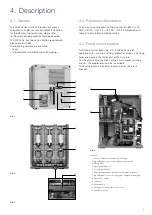
4.5. Preliminary operations
Clean the insulating parts with clean dry cloths.
Check that the top and bottom terminals are clean and free of
any deformation caused by shocks received during transport
or storage.
4.5.1. installation of fixed circuit-breakers
Vmax circuit-breaker can be fixed directly on the supporting
plate or on a truck provided by the customer. The customer
must guarantee a minimum degree of protection (IP2X) from
the front towards live parts.The fixed version of Vmax circuit-
breaker must be installed by the customer so as to guarantee
a minimum degree of protection as for C37.20.2 and C37.55
test requirements.
4.5.2. insertion and removal withdrawable circuit-breaker
This section describes the process for inserting the breaker
into the disconnect position of the switchgear and the
removal of the circuit-breaker from the disconnect position.
Racking of the circuit-breaker to and from the test and
disconnect position is covered in the following section.
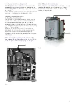
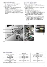
insertion
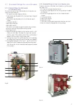
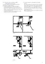
(Refer to Fig. 7 and 13)
(From withdrawn Position to Disconnect Position)
1. Align breaker and ramp, dolly or lift truck with circuit-
breaker compartment
2. Pull handles (17) to center (this withdraws Cell Interlock
Tabs (11) allowing breaker to be inserted)
3. Push breaker into breaker compartment with handles.
4. Align Cell Interlock Tabs with Circuit breaker Compartment
Slots (A)
5. Push Handles out to fully engage Cell Interlock Tabs into
Circuit breaker Compartment Slots
6. Visually check that Cell Interlock Tabs are engaged in
Circuit-breaker Compartment Slots (if Cell Interlock Tabs
are not fully extended, racking is prevented) breaker is now
in the Disconnect Position
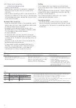
Removal
(Refer to Fig. 7 and 14)
(From Disconnect Position to withdrawn Position)
1. Visually check to see the Truck (11) is against the Locator
Channel
2. Pull Handles to center (this withdraws Cell Interlock Tabs;
allowing breaker to be removed .
4. Pull the breaker from Circuit-breaker Compartment with the
Handles onto the required transportation device.
4.5.3. withdrawable circuit-breakers with truck
made by third parties
The Vmax circuit-breakers installed on trucks made by the
customer must be fitted with one or two additional auxiliary
contacts (operated by the mechanical lock and by the circuit-
breaker release device) which are entrusted with the function
of interrupting the shunt closing release circuit (-MC).
In this way it is certain that no electrical impulse can activate
the shunt closing release with the circuit-breaker in an
intermediate position.
The customer must also provide a lock to prevent circuit-
breaker traverse when it is in the closed position.
4.5.4. installation of withdrawable circuit-breakers
in abb PowerCube modules
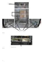
The withdrawable circuit-breakers are use in PowerCube
modules see Fig. 13 - 14.
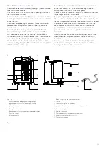
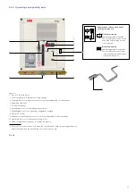
For racking-in/racking-out of the switchgear: connect the
secondary plug (14) (fig. 7) with secondary disconnector
(b) (fig.14) , fully insert the crank handle (1) (fig. 11 in the
appropriate seat) (2) (fig.11) and work it clockwise for racking-
in, and anti-clockwise for racking-out, until the end-of-run
positions are reached.
Circuit-breaker racking- in/-out must be carried out gradually
to avoid shocks which may deform the mechanical interlocks
and the end-of-runs.
The torque normally required to carry out racking- in and
racking-out is <25 Nm.
This value must not be exceeded. If operations are prevented
or difficult, do not force them and check that the operating
sequence is correct.
note
To complete the racking-in/out operation, 20 turns of the
crank handle are required.
when the circuit-breaker has reached the connect/
disconnect position it can be considered as racked into the
switchgear and, at the same time, earthed by means of the
truck wheels.
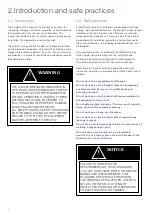
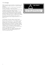
THE RACkING-IN/-OuT OPERATIONS
MuST ALwAyS bE CARRIED OuT wITH
THE CIRCuIT-bREAkER OPEN.


