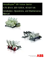
VersaRupter MV Indoor Switch | Installation and Operation Manual
12
Mounting the Open Fuse Auxiliary Switch
The open fuse auxiliary switch can only be installed on the A-
mechanism and a fuse base equipped with fuse tripping. This
switch has two contacts, one normally open and one normally
closed. It is actuated by the fuse tripping tie rod linkage con-
nected to the type CEF fuse base.
1. Locate the mounting hole and slot on the side of the A-
mechanism with the operating shaft shown in figure 11.
2. Bolt the open fuse auxiliary switch to the mounting hole on
the A-mechanism and loosely install the screw hardware to
allow the switch to rotate into the slot, pictured in figure
12.
3. Place the white disk onto the half-moon shaft and rotate
the switch into place as shown in figure 13.
4. Rotate the white disk with your finger and mark the hole
directly adjacent to the white roller on the switch as
shown in figure 14.
Figure 11
Figure 12
Figure 13
Figure 14
Содержание VersaRupter
Страница 59: ...VersaRupter MV Indoor Switch Installation and Operation Manual 59 Outline Drawing 8 25 kV 200 600 A 40 kA ...
Страница 60: ...VersaRupter MV Indoor Switch Installation and Operation Manual 60 Outline Drawing 8 25 kV 1200 A 40 kA ...
Страница 61: ...VersaRupter MV Indoor Switch Installation and Operation Manual 61 Outline Drawing 15 kV 200 600 A 40 kA ...
Страница 62: ...VersaRupter MV Indoor Switch Installation and Operation Manual 62 Outline Drawing 15 kV 1200 A 40 kA ...
Страница 63: ...VersaRupter MV Indoor Switch Installation and Operation Manual 63 Outline Drawing 15 15 5 kV 600 1200 A 61 kA ...
Страница 64: ...VersaRupter MV Indoor Switch Installation and Operation Manual 64 Outline Drawing 17 kV 200 600 A 40 kA ...
Страница 65: ...VersaRupter MV Indoor Switch Installation and Operation Manual 65 Outline Drawing 17 kV 1200 A 40 kA ...
Страница 66: ...VersaRupter MV Indoor Switch Installation and Operation Manual 66 Outline Drawing 27 kV 200 600 A 40 kA ...
Страница 67: ...VersaRupter MV Indoor Switch Installation and Operation Manual 67 Outline Drawing 27 kV 1200 A 40 kA ...
Страница 68: ...VersaRupter MV Indoor Switch Installation and Operation Manual 68 Outline Drawing 38 kV 600 800 A ...
Страница 69: ...VersaRupter MV Indoor Switch Installation and Operation Manual 69 Back Connect Kit 5 kV 200 600 A 40 kA ...
Страница 70: ...VersaRupter MV Indoor Switch Installation and Operation Manual 70 Back Connect Kit 15 kV 200 600 A 40 kA ...
Страница 71: ...VersaRupter MV Indoor Switch Installation and Operation Manual 71 Back Connect Kit 17 kV 200 600 A 40 kA ...
Страница 72: ...VersaRupter MV Indoor Switch Installation and Operation Manual 72 Back Connect Kit 27 kV 200 600 A 40 kA ...
Страница 73: ...VersaRupter MV Indoor Switch Installation and Operation Manual 73 Back Connect Kit 15 kV 600 A 61 kA ...
Страница 74: ...VersaRupter MV Indoor Switch Installation and Operation Manual 74 Auxiliary Switch Kit ...
Страница 75: ...VersaRupter MV Indoor Switch Installation and Operation Manual 75 Chain Drive Assembly ...
Страница 76: ...VersaRupter MV Indoor Switch Installation and Operation Manual 76 Left Hand Shaft Extension ...
Страница 77: ...VersaRupter MV Indoor Switch Installation and Operation Manual 77 Mechanical Door Interlock ...
Страница 78: ...VersaRupter MV Indoor Switch Installation and Operation Manual 78 Direct Drive Handle Right Side ...
Страница 79: ...VersaRupter MV Indoor Switch Installation and Operation Manual 79 Direct Drive Handle Left Side ...
Страница 80: ...VersaRupter MV Indoor Switch Installation and Operation Manual 80 HE HM Handles ...
Страница 82: ...VersaRupter MV Indoor Switch Installation and Operation Manual 82 Notes ...


