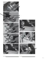
35
60
61
61
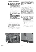
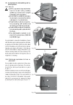
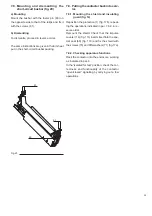
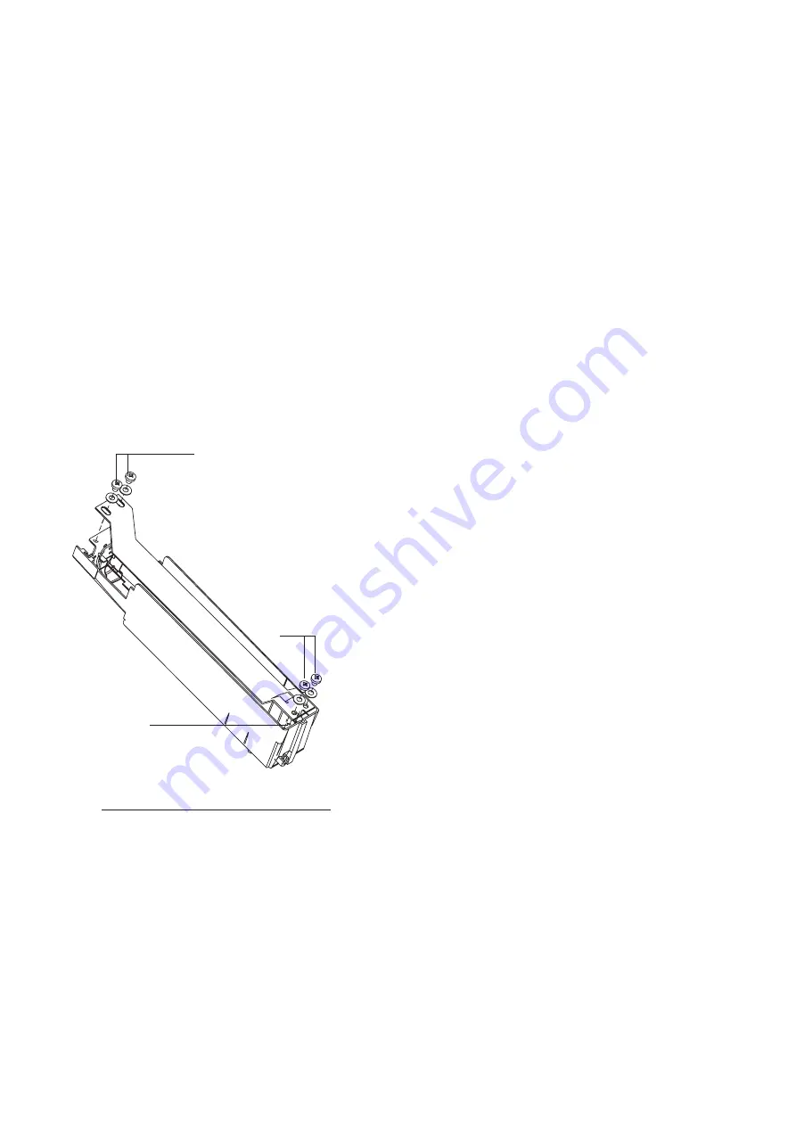
7.8. Mounting and dismantling the
short-circuit busbar (fig. 20)
a) Mounting
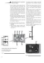
Mount the busbar with the feeler pin (60) on
the opposite side to that of the tulips and fix it
with the screws (61).
b) Dismantling
To dismantle, proceed in reverse order.
The same instructions are given in the Kit sheet
put in the short-circuit busbar packing.
Fig. 20
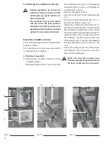
7.9. Putting the contactor back into serv-
ice
7.9.1. Mounting the shield and insulating
guard (fig. 14)
Reposition the protection (1) (fig. 17b), repeat-
ing the operations indicated in par. 7.6.2. in re-
verse order.
Remount the shield. Check that the impulse
counter (14) (fig. 17c) inserts itself into the spe-
cial seat (69) (fig. 17d) and fix the shield with
the screws (70) and DIN washers (71) (fig.17a).
7.9.2. Checking apparatus functions
Rack the contactor into the enclosure, working
as indicated in par. 6.
In the “isolated for test” position, check the cor-
rectness and functionality of the contactor
“open/closed” signalling by carrying out a few
operations.
Содержание V-Contact VSC Series
Страница 1: ...V Contact VSC Installation and service instructions 7 2 12 kV 400 A ...
Страница 2: ...1 ...
Страница 35: ...33 50 50 49 49 Fig 18c Fig 18b ...
Страница 39: ...1 ...

