


9
1ZSE 5492-128 en, Rev. 4
1 Introduction
1. Introduction
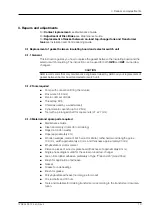
1.1 General
The UZ range of on-load tap-changers manufactured by ABB has been developed over
many years to provide maximum of reliability. The simple and rugged design gives a service
life equal to the service life of the transformer. Minimum maintenance is required for trouble-
free operation. The only parts requiring maintenance are contacts that might need replace-
ment during the service life, the insulating oil and the motor-drive mechanism.
The design allows excellent access to all parts, making inspection and maintenance quick
and simple.
The on-load tap-changer type UZE/UZF is placed in a oil filled tank separated from the
transformer tank. The motor-drive mechanism is attached to the side of the on-load tap-
changer tank.
1.2 Repair categories
Repairs on the UZ range of on-load tap-changers fall into two categories:
■
Repairs. Repairs are to replace worn or end-of-service-life parts.
■
Modifications. Modifications are only issued by ABB to improve the already very high
standard of reliability and to assist in prolonging the service life of the equipment.
The modifications fall into two areas:
■
Immediate, where the modification should be completed at the earliest possible oppor
-
tunity.
■
Routine, where the modification should be completed during a routine service.
1.3 Serial number
Before consulting ABB for technical advice to assist with repairs or to order spare parts to
complete the repairs, the on-load tap-changer serial number must be known. The serial
number can be found on the rating plate (figure 2 shows the location of the rating plate).
If the on-load tap-changer serial number cannot be obtained, the transformer serial number
should be used (only if the transformer is manufactured by ABB in Ludvika, Sweden).
NOTE: One of these serial numbers must be quoted in all correspondence and telefax
messages, and during any telephone conversations with ABB. Failure to use the serial
number may cause delays.
Содержание UZE
Страница 6: ......
Страница 8: ......
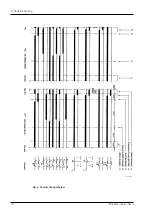
Страница 17: ...17 1ZSE 5492 128 en Rev 4 fm_00120 2 Trouble shooting Fig 3 Circuit diagram...
Страница 18: ...18 1ZSE 5492 128 en Rev 4 fm_00113 2 Trouble shooting Fig 4 Contact timing diagram...