ABB UZE Скачать руководство пользователя страница 7

Contents

1. Introduction

 _______________________________________________________9

1.1 General

 _______________________________________________________9

1.2 Repair categories

 _______________________________________________9

1.3 Serial number

 __________________________________________________9

1.4 Spare parts list

 _________________________________________________

10

1.5 Maintenance guide

 ______________________________________________

11

1.6 Tightening torque

 _______________________________________________

11

2. Trouble-shooting

 ___________________________________________________

12

2.1 On-load tap-changer

 ____________________________________________

12

2.2 Pressure relay

 __________________________________________________

12

  2  Trouble-shooting 

 _____________________________________________

13

2.3 Motor-drive mechanism

 __________________________________________

14

2.3.1 Control system

 _____________________________________________

14

2.3.2 Power system

 ______________________________________________

16

2.3.3 Miscellaneous

 ______________________________________________

16

3. Repairs and adjustments ____________________________________________

19

3.1 Replacement of gasket between insulating board and selector switch unit


19

3.1.1 General

 ___________________________________________________

19

3.1.2 Tools required

 ______________________________________________

19

3.1.3 Material and spare parts required

 ______________________________

19

3.1.4 Procedure

 _________________________________________________

20

3.2 Replacement of gaskets between barrier board of steel and

selector switch unit  _________________________________________________

22

3.2.1 General

 ___________________________________________________

22

3.3 Replacement of front cover and top cover gaskets ___________________

22

3.3.1 General

 ___________________________________________________

22

3.3.2 Tools required

 ______________________________________________

22

3.3.3 Material and spare parts required

 ______________________________

23

3.3.4 Procedure

 _________________________________________________

23

3.4 Changing the end stops in motor-drive mechanism

  __________________

23

3.4.1 General

 ___________________________________________________

23

3.4.2 Tools required

 ______________________________________________

23

3.4.3 Material and spare parts required

 ______________________________

24

3.4.4 Procedure

 _________________________________________________

24

3.5 Replacement of maintaining contact

 _______________________________

26

3.5.1 Tools required

 ______________________________________________

26

3.5.2 Spare parts required

  ________________________________________

26

3.5.3 Procedure

 _________________________________________________

26

3.6 Replacement of pressure relay

 ____________________________________

26

3.6.1 General 

 ___________________________________________________

26

3.6.2 Tools required

 ______________________________________________

26

3.6.3 Spare parts required

  ________________________________________

27

3.6.4 Procedure

 _________________________________________________

27

Содержание UZE

Страница 1: ...On load tap changers type UZE and UZF with motor drive mechanism type BUF 3 Repair guide 1ZSE 5492 128 en Rev 4...

Страница 2: ...This document must not be copied without our written permission and the contents thereof must not be imparted to a third party nor be used for any unauthorized purpose Contravention will be prosecuted...

Страница 3: ...l information to assist in carrying out the work de scribed Safety precautions WARNING Before any work is carried out on the on load tap changer Make sure that the transformer is disconnected and that...

Страница 4: ...s and selector switch housings contains harmful substances Fumes are irritating to the respiratory organs and the eyes and are very easily set on fire Used transformer oil may well be carcino genic Av...

Страница 5: ...tap changer is under vacuum and the transformer tank is not Mounting of gaskets CAUTION Sealing surfaces and gaskets must be clean and undamaged Diametrically opposed bolts in sealing joints must be...

Страница 6: ......

Страница 7: ...________19 3 1 4 Procedure__________________________________________________20 3 2 Replacement of gaskets between barrier board of steel and selector switch unit_______________________________________...

Страница 8: ......

Страница 9: ...epairs Repairs are to replace worn or end of service life parts Modifications Modifications are only issued by ABB to improve the already very high standard of reliability and to assist in prolonging...

Страница 10: ...otor Drive Mechanism type BUF 3 The Spare Parts List also contains several exploded views which can be very handy when making repairs 1 Introduction Lifting eye Connection to oil conservator On load t...

Страница 11: ...he Maintenance Guide Contact replacement is also described in the Main tenance Guide Since references are made to the Maintenance Guide you will need the Maintenance Guide 1 6 Tightening torque The fo...

Страница 12: ...l according to Correct Oil Level in the Installation and Commissioning Guide and then rechecking some time later Low oil level alarm A lowering oil level in the on load tap changer may indi cate a lea...

Страница 13: ...e pressure relay housing to earth Short circuit the four terminals and apply test voltage 500 2000 V on them for one minute Remove the shortcir cuit from the terminals and reconnect the wires from the...

Страница 14: ...from dust and oxide Check the contact function with the moving contact arm in all positions 2 Check the resilience of the moving contact in the multi position switch The clearance between the nut and...

Страница 15: ...ide 3 Check that the flywheel stops in its middle position with a tolerance of 30 degrees For information about adjusting the brake refer to section Disc Brake in Maintenance Guide 4 Check that the ra...

Страница 16: ...angerous voltage 2 3 3 Miscellaneous Error condition Fault finding procedure Corrosion and or condensation in the motor drive mechanism cabinet Check the function of the heater Refer to Heater in Main...

Страница 17: ...17 1ZSE 5492 128 en Rev 4 fm_00120 2 Trouble shooting Fig 3 Circuit diagram...

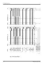
Страница 18: ...18 1ZSE 5492 128 en Rev 4 fm_00113 2 Trouble shooting Fig 4 Contact timing diagram...

Страница 19: ...tting the oil valve Box wrench 19 mm Electric drill set of drills Thread tap M16 Chisel as used by a woodworker Dynamometric wrench up to 42 Nm Tool with a prolonged shaft for square nuts 27 x 27 mm 3...

Страница 20: ...ethreaded M16 8 The phase unit now stays in place by the glued gasket Make some arrangement in order to prevent it from tilting out when coming loose from the board e g by using a rope between the pha...

Страница 21: ...e middle of the three nuts for one clamp Tighten with 5 15 Nm first and thereafter twice with 22 Nm NOTE Do not retighten the nuts 14 Retighten all the nuts around the edge of the barrier board with a...

Страница 22: ...Replacement of gaskets between barrier board of steel and selector switch unit 3 2 1 General Follow section 3 1 where applicable and with following exceptions Distance pieces of wood or pressboard thi...

Страница 23: ...re of the washer with earthing snag placed on one of the stud bolts 4 Clean the gasket surfaces Replace the gasket with a new one The gasket is not glued The gasket surface against the cover is coated...

Страница 24: ...lower end stop in the following way Operate to the new lowest position 1 Mark up the first hole below the pivoting arm Fig 9 Operate the on load tap changer to a position where the marked hole is acc...

Страница 25: ...ble and mount another extra stop screw 3 Operate the motor drive mechanism using the hand crank and check that the mechani cal end stops work and with motor operation that the electrical limit switche...

Страница 26: ...sition as on the old one 3 Shift the conductors from the old switch to the new one 4 Loosen the old switch and mount the new switch CAUTION The lever with the roller inside the mechanism should be hor...

Страница 27: ...oupling and remove the pressure relay 4 Install a new O ring 17 1x1 6 mm 5 Lubricate the threads of the connection nut with grease 6 Mount the new pressure relay Tightening torque 25 Nm 7 Carry out th...

Страница 28: ...nents SE 771 80 Ludvika Sweden Phone 46 240 78 20 00 Fax 46 240 121 57 E Mail sales se abb com www abb com electricalcomponents Contact us Copyright 2010 ABB All rights reserved 1ZSE 5492 128 en Rev 4...

Отзывы: