


Electrical
connection
CI/TTH200-EN
TTH200
EN - 15
4.4
Standard application
s
Field
Control
room
A
B
+
-
U
M
+
U
S
-
R
Ltg
A00094
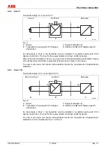
Fig. 8
A Transmitter
B Supply isolator/PLC input with supply
When connecting these components, observe the following condition:
U
Mmin
≤
U
Smin
+ 0.02 A x R
Ltg
Where:
U
Mmin
:
Minimum operating voltage of transmitter
U
Smin
:
Minimum supply voltage of repeater supply isolater / PLC input
R
Ltg
:
Line resistance between transmitter and supply isolator
For HART functionality, use supply isolators or PLC input cards with HART mark. If this is not
possible, the interconnection must have a resistance
≥
250
Ω
(< 1100
Ω
).
The signal line can be connected with or without ground. When connecting the ground (minus
side), make sure that only one side of the contact is connected to the equipotential bonding
system.
4.5
Standard application with HART functionality
Field
Control
room
A
B
+
-
U
M
+
U
S
-
R
Ltg
A00095
R
250
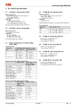
Fig. 9
A Transmitter
B Supply isolator/PLC input with supply
Adding resistance R
250
increases the minimum supply voltage:
U
Mmin
≤
U
Smin
+ 0.02 A x (R
Ltg
+ R
250
)
Where:
U
Mmin
:
Minimum operating voltage of transmitter
U
Smin
:
Minimum supply voltage of repeater supply isolator / PLC input
R
Ltg
:
Line resistance between transmitter and supply isolator
R
250
:
Resistance for HART functionality


