Commissioning
2-18
Assembly instructions
•
The spraying device wets the torch head with an anti-adhesion fluid which prevents early depo-
sition of new weld spatter.
•
The period of spraying is fixed in the program. Two short sprays is better than one long spray.
The spraying process is over when the time runs out.
•
If there is no wire-cutting program, the robot runs into the basic setting and reports end of pro-
gram and readiness to start for continued running through the welding program.
•
The screen of the spray nozzle can be removed for cleaning purposes.
2.5.5.3 Wire
cutting
(option)
The robot is in the basic setting. The welding torch is generally inside the torch cleaner, above the
spray head.
After a wire-cutting program contained in the rotor is called
•
the cutting knife is opened
•
the clamping cylinder also closes automatically, as the two motions are linked.
•
The knife closes and cuts the welding wire to the desired wire length distance. The knife and
clamping cylinder are then back in their basic position.
•
The robot runs into the basic setting and reports end of program and readiness to start for con-
tinued running through the welding program.
A detailed description of the wire cutter can be found in
.
2.5.5.4
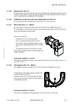
TCP gauging (option)
Gauging of the TCP (Tool Center Point) is optionally included in the robot program and is per-
formed automatically. It is recommended that the TCP is also re-gauged after each torch cleaning
operation.
A detailed description of TCP gauging can be found in
Chapter 4 TCP gauging (BullsEye
.
•
The welding torch runs to the desired wire length
distance (e.g. 10 mm) above the knife into the wire-
cutting position of the torch cleaner.
•
The wire feed advances a welding wire surplus
length of
at least 20 mm
!
(A surplus wire length of at least 20 mm is neces-
sary to avoid disturbance of operation due to wire
waste.)
Wire length distance
Surplus wire length
>20mm
Содержание TSC 2013
Страница 1: ... ROBOTICS Assembly instructions Torch Service Center TSC 2013 ...
Страница 6: ...Contents 3HDA000057A8519 001 I 6 ...
Страница 10: ...1 4 3HDA000057A8519 001 Torch Service Center TSC 2013 Assembly instructions ...
Страница 56: ...Electrical circuit diagram 2 36 3HDA000057A8519 001 Torch cleaner TC 2013 Assembly instructions ...
Страница 78: ...Dimension sheet Gas nozzle 5 2 3HDA000057A8519 001 Appendix Assembly instructions ...
Страница 87: ......


