


PN25080
Start-Up & Operation 5 - 1
TRIO-WIRL INSTRUCTION MANUAL
CHAPTER 5 Start-Up & Operation
5.1 Start-Up
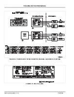
Prior to initial system start-up, verify that the meter is
properly installed. Check flow direction as indicated on
the meter body and wiring interconnections as shown
in Figures
Verify that the power supply is the correct value
according to the power requirements of the signal con-
verter and that it is connected with the proper polarity.
If everything is properly installed and connected, turn
on the power to the meter. The LCD display should
become active and display the selected information in
two lines.
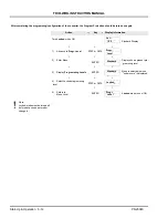
Using the pushbuttons located in the signal converter
housing (see Section
), verify that the correct oper-
ating parameters have been entered as described in
this section.
If everything appears to be operating properly, initiate
process flow through the flowmeter. Flow measure-
ment and output signal transmission should begin as
the process fluid flows through the meter.
5.1.1 Calibration Parameters
The TRIO-WIRL flowmeter is precision-calibrated at
the factory for the values specified at the time of order.
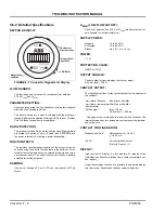
The meter data is noted on a paper data tag located on
the customer connection lid. A metal data tag is located
on the outside of the instrument with additional data. A
sample of this tag is shown in Figure
5.1.2 Firmware Version
The firmware level and the model number are shown in
the display with the model number and firmware
release date on the top line and the EPROM identifica-
tion and firmware level on the bottom line. Changes to
the firmware can only be made by replacing the
EPROM. When communicating with ABB Inc., please
reference the firmware version of the instrument.
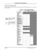
The Functional Flowchart shown in Figure 4-1 gives a
pictorial overview of the top-level menu structure of this
version of firmware. Functions of these menu parame-
ters and their sub-menu breakdowns are explained in
more detail following the flowchart.
This procedure has been prepared based on firmware
version
699F004U01 A.11
. Other versions will be simi-
lar, but not identical and may have features different
from those discussed in this section.
5.1.3 Program Protection
The Program Protection is automatically turned ON
during power-up. Parameters cannot be changed when
Program Protection is ON. Refer to Section
change Program Protection from ON to OFF (or
vice-versa).
5.1.4 Error Messages
Error messages replace the flow rate indication in the
top line of the display when certain failure conditions
exist or when an attempt has been made to enter an
unacceptable value.
Refer to Chapter
for definitions of displayed error
messages.
5.2 Electrical Interconnections
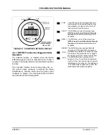
5.2.1 TRIO-WIRL VT/ST4000 Integral
The flow metering system TRIO-WIRL is designed as a
2-wire instrument, i.e. the supply power and the current
output signal (4-20 mA) both use the same pair of con-
nection leads as shown in Figure
FIGURE 5-1 INSTRUMENT DATA TAG
Ref.
-r.


