


PN25080
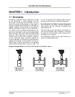
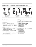
Swirlmeter
(TRIO-WIRL S) 2 - 5
TRIO-WIRL INSTRUCTION MANUAL
Mounting bolts and nuts are supplied by the user
.
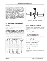
During installation, make certain that the flow direction
arrow on the meter body is oriented in accordance with
the process flow.
With the meter safely supported, install the bolts
through the meter and process flanges. Bolts and nuts
should be lubricated with a graphite based lubricant.
Assemble the nuts to the bolts hand tight. Tighten the
flange nuts in a diagonal or "star" pattern as shown in
Figure
to equalize pressure on the flange face and
gaskets. Bolt/nut torque should be limited to that which
will provide a leakproof seal.
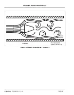
2.4.2.3 Control Valve Installation
Control valves should preferebly be installed down-
stream from the flowmeter as shown in Figure
.
When this is not possible, the control valve should be
located > 3D upstream of the flowmeter.
2.4.2.4 Extreme Temperature Applications
For process temperatures above 160
o
F (71
o
C) or
below 0
o
F (-18
o
C), it is critical that the meter be pres-
surized and placed into service gradually, i.e., with suf-
ficient time delay to minimize thermal shock. Steam
should be introduced gradually so that the meter is
brought up to operating temperature over a ten to fif-
teen minute period.
FIGURE 2-3 METER PIPING REQUIREMENTS
FIGURE 2-4 RECOMMENDED FLANGE BOLT
TIGHTENING SEQUENCE
Refer to Figure
3D
FIGURE 2-5 CONTROL VALVE INSTALLATION


