


Operation Manual / TPS50
5 Maintenance / 5.2 Cleaning the compressor during operation
© Copyright 2021 . All rights reserved.
HZTL2401_EN
Rev.A
September 2021
u
Push the valve activator (Y) against the spring and hold it for 10 to 15
seconds until entire volume of water has been injected.
u
After cleaning, wait at least 5 minutes with the engine running to al-
low the turbocharger to dry.
u
The cleaning cycle may only be repeated after a stabilisation period of
at least 10 minutes has elapsed.
NOTICE
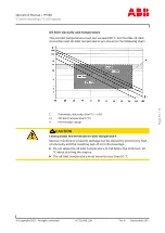
Whether or not cleaning has been successful can be seen from the char-
ging or flushing pressure and also from the exhaust gas temperatures.
If the cleaning operation is not satisfactory, it can be repeated up to
two times.
If the cleaning result is still not satisfactory after three attempts and
the engine values are also unsatisfactory, we recommend that the tur-
bocharger be inspected and cleaned by an official ABB Turbocharger
service station.
Cleaning parameters per
turbocharger compressor
Turbocharger
type
Turbocharger
speed
Contents of
water container
[dm
3
]
Water
injection time
t
1
[s]
TPS 50
approximately
n
Bmax
0.4
4 … 10
Page
37
/
71


