background image

11 

PCCU32 Connectivity 

RS-232 Local Connect 

The RS-232 local connection requires a serial port on the host computer 

(generally a laptop). A PCCU cable is required to connect the host 

computer to the flow meter’s round military connector. Connecting the 

PCCU cable to the flow meter will cause an annunciator in the LCD to 

display an upper case letter “L” for local connect. To connect PCCU32 to 

the meter, click the Connect to Totalflow icon on the toolbar. To connect 

and move directly to Entry mode, click on Entry instead of the Connect 

icon. 

If the meter has been given a security code, the user needs to ensure 

that they have entered that code in the PCCU32 System Setup screen. 

The factory default for a security code is 0000. Cold starting the meter 

re-establishes the 0000 security code; however, cold starting the meter 

also deletes historical data. 

USB Connectivity 

Note: 

USB connectivity requires PCCU32 version 7.17 or higher.


The first time that the user connects their laptop to a G4 meter using the 

USB connectivity, the appropriate drivers need to be installed. 

A


Connect the G4 meter (XFC/XRC) to the laptop. After a couple 
of seconds the “Found New Hardware Wizard” will appear. It 
will ask if, “Windows should connect to Windows Update and 
search for software?” 

Select “No, not this time” and click “Next” to continue. 

B


The next dialogue box will ask, “What do you want the wizard 
to do?” 


Select “Install the software automatically (Recommended)” and 
click “Next” to continue. 

C


At this point you will get a Microsoft® message warning that 
the Totalflow USB driver has “not passed Windows Logo 
testing”. If you want to use your laptop’s USB port you will 
need to click on “Continue Anyway” and proceed with the 
installation. 

D


The “Found New Hardware Wizard” has finished. Click 
“Finish”. The Totalflow USB driver is now installed.  

NOTES: 

The above procedure creates a virtual com port on the laptop. 

The com port disappears when the meter is disconnected. 

The com port can be seen to appear and disappear in the 

Device Manager whenever the USB cable is connected or 

disconnected from the laptop. 

Содержание TOTALFLOW X G4 Series

Страница 1: ......

Страница 2: ...he start up of the XFCG4 flow computer or XRCG4 remote controller series The start up guide however is primarily intended for gas orifice applications Using this guide in conjunction with other drawings and documentation that accompany the user s order should result in a smooth installation If there are additional questions that are not answered by this guide or other provided documentation the us...

Страница 3: ...t Figure 2 Pipe Mounts 1D Mount the manifold to the bottom of the unit The right port of the unit is normally high pressure upstream side Check the XIMV model number to verify that it is designed for flow from left to right 4 CYC or right to left 4 AYC The user can look on the transducer for H or for high side and L or for low side For direct mount manifolds the direction is very important See Fig...

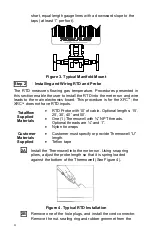
Страница 4: ... RTD inputs Totalflow Supplied Materials RTD Probe with 10 of cable Optional lengths 15 25 30 40 and 50 One 1 Thermowell with NPT threads Optional threads are and 1 Nylon tie wraps Customer Materials Supplied Customer must specify or provide Thermowell U length Teflon tape 2A Install the Thermowell into the meter run Using snap ring pliers adjust the probe length so that it is spring loaded agains...

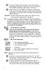
Страница 5: ...eriesG4 main electronic board Loosen the terminal block securing screws insert the wire and then retighten see Figure 5 Reinstall the terminal block with the wires attached Figure 5 RTD Terminal Block Wiring Step 3 Battery Installation 3A To extend the life of a battery pack fully charge the battery prior to installation A system using solar panels may not fully charge the battery Also a fast char...

Страница 6: ...Lithium Battery Connection 4A G4 units are shipped from the factory with the lithium battery jumper in the Disabled position Verify that the Memory Backup is set to enabled with a jumper on the upper two pins of J13 on the XFCG4 or J1 on the XRCG4 In Station Setup verify that the Lithium Battery Status is OK If the status is not OK the lithium battery is below 2 5 volts and should be replaced Step...

Страница 7: ...osure and install the cord connector Remove the nut sealing ring and rubber grommet from the cord connector Slide the nut sealing ring and grommet over the cable and insert the cable through the body of the cord connector Allow enough cable to extend into the unit for the connection to the charger input terminals located on the main electronic board XFCG4 terminal block J5 or XRCG4 terminal block ...

Страница 8: ...ss valves are open during the AP calibration to avoid a false DP Make sure there are no leaks in the manifold or test equipment Perform as left calibration checks as needed 6E Place the unit online To avoid inducing toggle and or a calibration shift close the vent valve open the bypass valve and then open the orifice tap valves slowly high pressure side first Once both orifice tap valves are fully...

Страница 9: ...9 Figure 8 XFCG4 Layout NOTE Refer to the Wiring Interconnect drawing 2015225 WI for more information on communication wiring ...

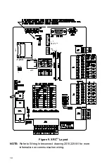
Страница 10: ...10 Figure 9 XRCG4 Layout NOTE Refer to Wiring Interconnect drawing 2015225 WI for more information on communication wiring ...

Страница 11: ...first time that the user connects their laptop to a G4 meter using the USB connectivity the appropriate drivers need to be installed A Connect the G4 meter XFC XRC to the laptop After a couple of seconds the Found New Hardware Wizard will appear It will ask if Windows should connect to Windows Update and search for software Select No not this time and click Next to continue B The next dialogue box...

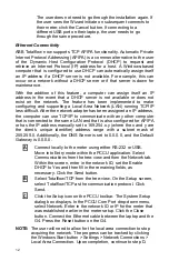
Страница 12: ...ommunicate with any other computer that is connected to the same LAN and that is also configured for APIPA or has the IP address manually set to 169 254 x y where the x and y are the client s unique identifier address range with a subnet mask of 255 255 0 Additionally the DNS Server is set to 0 0 0 0 and the Default Gateway is 0 0 0 0 A Connect locally to the meter using either RS 232 or USB Move ...

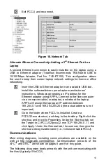
Страница 13: ...omputer via a crossover cable or adaptor and reboot the laptop APIPA will assign the laptop an IP address between 169 254 0 1 and 169 254 255 254 the actual address is not important B Go to the folder where PCCU is installed Create a PCCU32 exe shortcut and drag to the desktop Right click the shortcut and move to Properties Under the Shortcut tab set the Target to C PCCU32 pccu32 exe TCP 169 254 0...

Страница 14: ...ault indicates Comm 1 port is active The data bits stop bits and all required communications parameters can be modified with PCCU32 Units will typically be shipped with correct default comm port settings but may need fine tuning for optimum operation Warning As opposed to the XRCG4 the XFCG4 has only one Switched V Batt Operate line if it is needed Enable it only on one Comm Port even though both ...

Страница 15: ...tance Check two wires at a time from one unit to another If black and white wires are to be tested disconnect both wires at both ends set one probe on black the other on white The meter should read OL or OFL over range if no shorts Jumper the two wires at the other end The meter should read a low resistance if no opens This method requires only one end of wiring to be tested no matter how far the ...

Страница 16: ...r clock DATE TIME MM DD YY HH MM SS Yesterday s Percent DP Low Limit Percent time below DP Low Set Point Yest DP Low NN PERCENT Yesterday s Percent DP High Limit Percent time above DP High Set Point Yest DP High NN PERCENT Current Flow Rate Programmable SCF MCF or MMCF Flow Rate NNNNNN N SCF HR Total Accumulated Volume Programmable SCF MCF or MMCF Total Accum Volume NNNNNN NN MCF Battery Voltage D...

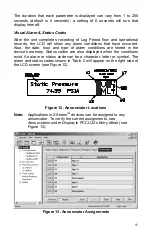
Страница 17: ...hour and type of alarm conditions are stored in the device s memory Status codes are also displayed when the conditions exist An alarm or status code can be a character letter or symbol The alarm and status codes shown in Table 2 will appear on the right side of the LCD screen see Figure 12 Figure 12 Annunciator Locations Note Applications in XSeriesG4 devices can be assigned to any annunciator To...

Страница 18: ...if this remote port is active and running Totalflow Remote Protocol Flashes in sync with listening cycle that occurs at 1 2 or 4 second intervals M MODBUS ASCII Modbus ASCII protocol is selected for this port m MODBUS RTU Modbus RTU protocol is selected for this port L Local Protocol Displayed when PCCU32 port is active and running Totalflow Local Protocol Packet Protocol Totalflow Packet Protocol...

Страница 19: ...o determine where the alarm condition is present A D A to D Failure Displayed if A to D Converter s Differential Pressure Absolute Static Pressure or temperature readings exceed maximum counts or are less than minimum counts The Display Does Not Scroll As Expected When power is first applied the unit should quickly go through startup and begin cycling through the pre programmed display items If th...

Страница 20: ...ABB Inc Totalflow Products 7051 Industrial Blvd Bartlesville Oklahoma 74006 Tel USA 800 442 3097 International 001 918 338 4880 ...

Отзывы: