


S P I R I T
I T
F L O W - X
I N S T R U C T I O N M A N U A L | I M / F L O W X - E N
2 3
Caution
Analog inputs do not have overvoltage and overcurrent
protection in order to meet the high accuracy specifications.
Digital signals
Each Flow-X/M module provides 16 general-purpose digital
channels that are all sampled and processed at 10 MHz.
Each channel can be individually and independently configured
as one of the following type of digital I/O:
Digital input
Digital output
Pulse input
Time period input (typically used for densitometers)
Pulse output (for driving electro-mechanical counters)
Detector input (for meter proving)
Prover bus output (to support separate prover flow
computers)
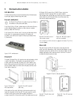
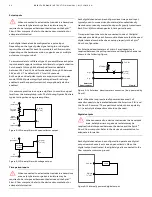
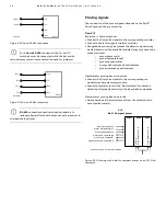
The following schematic illustrates the electrical circuit as used
for each digital signal
Figure 6-9 Digital channel circuit
Each digital channel has two field terminals, one terminal for the
signal itself and one ground terminal. The ground terminal is
only to be used when required by the application. All ground
terminals are internally connected to the main power return
terminal.
Each digital input channel supports two threshold levels for
signal activation. For digital channels 1 through 8 the threshold
level is selectable between 1.25 V and 12 V and for channels 9
through 16 between 3.6 V and 12 V. The default is 12 V for all 16
channels.
An 8 ms debounce filter is used to filter on digital status input
signals, such as valve positions. Both the unfiltered and filtered
signals are available in the software.
The FET is used for output signals and connects the input signal
to the common ground. When the channel is configured as an
input, the FET will be left in the open state permanently.
Digital inputs
When connected to a device that resides in a hazardous
area, safety barriers or galvanic isolators may be
required to be interposed between the device and the Spirit
IT
Flow-X flow computer. Refer to the device documentation for
adequate information.
Each of the 16 digital channels of a Flow-X/M flow module can be
configured to operate as a digital input.
Digital inputs are sampled at 20 MHz, so all 16 channels can be
used for fast signals such as prover detector switches.
The digital input signal is sampled both unfiltered and with an 8
ms debounce period, which effectively ignores any state
changes shorter than 8 ms.
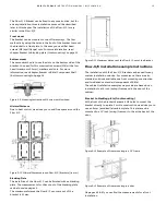
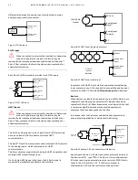
The digital input circuit can be either externally or internally
powered.
Because the digital inputs are floating, an external pull-up
resistor is required if the loop is internally powered.
Figure 6-10 Internally powered digital input
When externally powered, the external source should have a
connection to the common ground of the Spirit
IT
Flow-X flow
computer (“0 V"). Only when this is not already arranged
externally, an additional connection is required as shown in the
following figure. Also a pull-up resistor may be required
depending on the application.
Figure 6-11 Externally powered digital input
FET
Vref
1.2, 3.5
or 12V
Debounce
filter
0V
Digital
[1..16]
Unfiltered signal
(used for all
type of inputs)
Filtered signal
(used for digital
input only)
Digital
[1..16]
24V out
0V
Pull-up
resistor
(min. 470
Ohm,
typically 10
or 47 kOhm)
+V
(external)
Digital [1..16]
Pull-up
resistor
0V
0V
(external)


