Mounting
CI/FMT500-IG-EN
Sensyflow FMT500-IG
EN - 27
4.7
Aligning the housing head and display
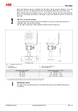
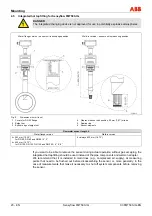
In the case of the integral mount design, the transmitter housing has been pivot-mounted to
make the display easier to read. From the center position it can be rotated by approximately
170° to the right or the left as far as the limit stop. The three grub screws can be tightened to
secure it (see Fig. 16).
The display orientation can be changed in increments of 90°. To do this, unscrew the front
housing cover (not in potentially explosive atmospheres) and remove the display cover. In the
case of devices with explosion-proof design, the safety locking device for the cover must be
released before removing the front housing cover.
WARNING
Do not open the front housing cover in potentially explosive atmospheres.
Risk of explosion! This can result in severe injuries or death.
Before opening the front cover, you must disconnect the device from the supply.
Always take ESD precautions before touching modules.
Once you have released the four mounting screws, remove the display panel and reinsert it in
the desired position. Then retighten the mounting screws, attach the display cover and screw on
the housing cover. In the case of devices with explosion-proof design, the safety locking device
must be reinstalled.
Fig. 16: The display can be rotated in increments of 90°.
1
Front housing cover
2
Display cover
3
Push buttons
4
Display panel
5
Grub screw
6
Rear housing cover


