background image

Operating instruction

42/14-37 EN

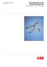
Thermal Mass Flowmeter

FMT200-D (Sensyflow D)

for compressed air, nitrogen and biogas

Содержание Sensyflow D

Страница 1: ...Operating instruction 42 14 37 EN Thermal Mass Flowmeter FMT200 D Sensyflow D for compressed air nitrogen and biogas ...

Страница 2: ...e 2 63755 Alzenau GERMANY Tel 49 551 905 534 Fax 49 551 905 555 CCC support deapr de abb com Copyright 2008 by ABB Automation Products GmbH We reserve the right to technical amendments This document is protected by copyright Information in this document is intended only to assist the user in safe and efficient operation of the equipment Its contents are not to be reproduced in full or part without...

Страница 3: ...essure Devices 7 3 Design and function 9 3 1 Pipe components 9 3 2 Transducer detecting element 10 4 Mechanical installation 11 4 1 Important information to begin with check list 11 4 2 Place of installation 11 4 3 Recommended steadying run lengths for inlet run disturbances 12 4 4 Installation 13 4 5 Weld on adapter for FMT200 D Sensyflow D transducers 14 5 Electrical installation 16 6 Start up S...

Страница 4: ...or contact our technical user assistance hotline directly For all questions concerning the measuring system please have the calibration certificate readily at hand Symbol Signal Word Definitions DANGER DANGER indicates an imminently hazardous situation which if not avoided will result in death or serious injury High level of risk WARNING WARNING indicates a potentially hazardous situation which if...

Страница 5: ...ed by DANGER WARNING CAUTION or NOTICE must be observed Otherwise personnel might be endangered and the mass flow meter itself or other devices and equipment could be damaged Prerequi sites for safe operation These operating instructions contain important information about the safe and proper operation of the equip ment Observing these instructions is mandatory for safe operation Failure to observ...

Страница 6: ...y measures If the devices are used in areas where dusts can cause explosion hazards you must clean the devices frequently Use genuine spare parts only 2 2 2 Notice according to the German Hazardous Material Directive According to the German Waste Disposal Act dated 1986 08 27 AbfG 11 Special Waste the owner of special waste is responsible for its disposal According to the German Hazardous Material...

Страница 7: ...e of the plant and checked accordingly The used materials must be checked by the user for compatibility with the respective application The max temperature and pressure specified on the rating plate must not be exceeded Prior to mounting or dismounting the pipe components or transducers always make sure that the pipe is fully depressurized Prior to starting any installation work on pipes with aggr...

Страница 8: ...nting the pipe components close the insertion pipe with an appropriate blind flange with gasket or close the existing stop valve if applicable 2 2 3 3 Mounting Dismounting the transducer When mounting the transducer make sure that its specifications are in accordance with the specifications of the measuring point Exclusively use the flawless media resistant gasket seal delivered with the transduce...

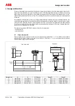
Страница 9: ... that clearly deviate from this gas composition must be ordered with a special calibration for biogas In this case the exact gas com position is to be specified with the order The measuring systems FMT200 D consist of only the 2 components transducer and pipe component 3 1 Pipe components Pipe components are available in various types for nominal pipe widths from 1 3 In addition it is possible to ...

Страница 10: ...nical Data 3 2 Transducer detecting element The detecting element which is designed as a plug in sensor contains apart from the sensor unit the completely cast transmitter circuit installed in the connection head This is mainly composed of the passive part of the dif ferential temperature controller for the sensor elements a memory for all parameter related measuring points the connector for the L...

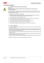
Страница 11: ...been complied with 5 Is the installation between detecting element and pipe component correctly done 6 Are the used sealings in their correct positions and in good condition 7 Have the electrical connections UIN 24 V and IOUT 0 4 20 mA been correctly made 4 2 Place of installation The installation site must fulfill the requirements stated in the chapter Technical Data Operating Conditions Environm...

Страница 12: ...r length de pends on the type of the inlet run disturbance Recommended steadying lengths according to DIN EN ISO 5167 1 To achieve the stated measuring accuracy the steadying lengths seen above must be provided The inlet and outlet run lengths are stated as multiples of the pipe diameter D For combinations of inlet run disturbances e g valve and reducer you must always consider the longer inlet ru...

Страница 13: ...ed at the outlet run length i e behind the measuring point 4 4 Installation The installation is described using the example of a pipe component The description analogously also applies to the installation using a weld on adapter 1 The flow direction must agree with the direction shown by the arrow on the pipe component 2 The opening diameter of the sealings used may not be changed and should on co...

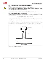
Страница 14: ...dapter must have a length L after welding see Fig 4 1 Thus a measuring position in the pipe centre will be achieved L H1 Ø D outside with H1 120 mm 4 72 The weld on adapter must be shortened to the corresponding length before welding The distance H1 from the upper edge of the adapter to the the pipe central axis must be within a tolerance of 2 mm 0 08 b For outer pipe diameters from 150 250 mm 6 1...

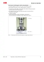
Страница 15: ...f the adapter must be aligned in flow direction to the pipe axis exactly at outlet run length behind measuring point 4 After welding the free passage for inserting the transducer must be at least 28 mm if required use drill to clear 5 Transducer installation Insert the supplied gasket into the provided groove of the transducer Push the transducer into the adapter and screw it together with the cap...

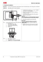
Страница 16: ... isolated 4 Analog output 0 4 20 mA electrically isolated 1 A shielded four wire cable e g 4 x 1 mm2 AWG 18 is required to connect the detector 2 Remove the connecting head cap of the detector by undoing the 4 screws 3 Connect the four wires to the terminal of the detector electronic unit see Fig 5 2 CAUTION Electrical isolation is only safeguarded when terminal 4 is not connected to terminal 2 of...

Страница 17: ...ply 24 V Step Action 1 Check whether the operating voltage specified on the device matches the power supply voltage 2 Use a power supply line with sufficient dimensions and ratings recommended line safety switches as of 2 A slow blow 3 Provide a mains switch or switchable power socket close to the device to be able to disconnect the device from all power if required Mark the mains switch according...

Страница 18: ...r power on the device is automatically in operation Step Check 1 Is the unit securely fastened 2 Are the electrical signal control and interface cable laid and connected correctly 3 Do the operating data of the existing measuring point correspond to the data stated on the calibration certificate e g medium operating temperature pressure measuring range 4 Have the permissible ambient temperatures b...

Страница 19: ...ult The following settings will be possible in case of fault MIN 3 5 mA MAX 22 5 mA Notice The standard setting in case of fault is 0 20 mA for MAX and 4 20 mA for MIN These settings can be modified via the LKS interface and the respective configuration software Further fault messages e g data error can be received via the status function Check function chapter 7 The following parameters can be ch...

Страница 20: ...er transport under unfavorable conditions 1 Switch off the supply voltage 2 Remove the detector from the pipe component or weld on adapter make sure that the pipe is not under pressure 3 Messwertaufnehmer aus dem Rohrbauteil bzw Aufschweißadapter ausbauen 4 Clean carefully the sensor unit with warm water or alcohol We recommend the use of a soft brush or a cotton tipped stick CAUTION Under no circ...

Страница 21: ...mary Stainless steel e g 1 4301 Pipe component with external threads R 1 3 Galvanized steel Pipe component with connection flanges DN 25 DN 80 Stainless steel e g 1 4301 Weld on adapter Stainless steel e g 1 4301 Connection flange according to EN1092 1 Form B1 PN40 Power supply Voltage 24 V AC DC 25 Power consumption 15 W Current consumption 600 mA slow blow fuse of at least 2 A recommended cable ...

Страница 22: ...x must be handled with care and has to be labeled accordingly For overseas shipment always add a desiccant e g silica gel and wrap the device and the desiccant bag in apolyethylene foil of 0 2 mm Adapt the amount of desiccant to the packing volume and the expected transport time at least sufficient for 3 months Additionally line the box with a layer of union paper Without exception all returned AB...

Страница 23: ...755 Alzenau Germany Tel 49 551 905 534 Fax 49 551 905 555 CCC support deapr de abb com ABB Inc 125 E County Line Road Warminster PA 18974 USA Tel 1 215 674 6000 Fax 1 215 674 7183 ABB has Sales Customer Support expertise in over 100 countries worldwide www abb com flow The Company s policy is one of continuous product improvement and the right is reserved to modify the information contained herein...

Отзывы: