


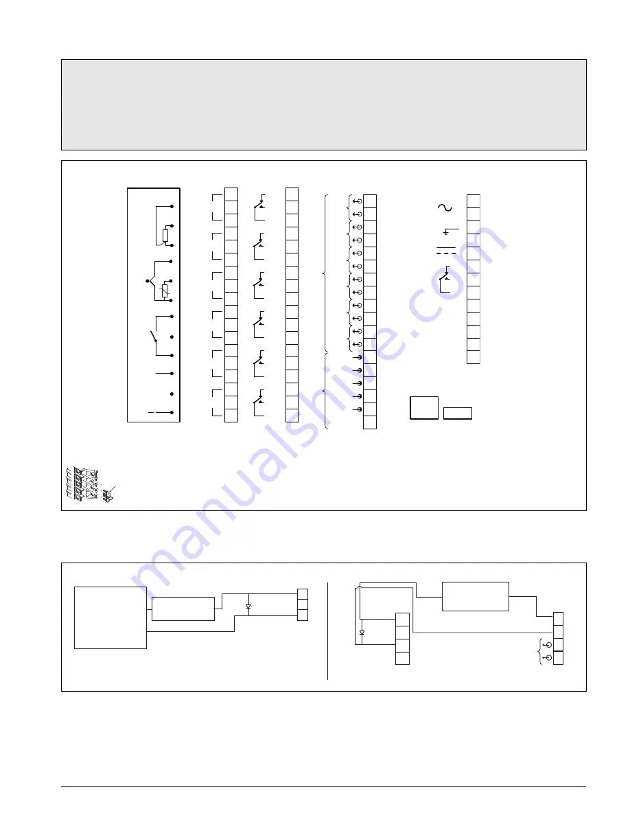
Analog input / relay / hybrid connections
Connecting a 2-lead temperature transmitter
Notes.
Tighten terminal screws to a torque of 0.1 Nm (0.9 lbf.in).
Analog inputs:
–
3-Lead RTD: 3-leads must have equal resistance, not exceeding 20
each
–
for mA input types, to ensure loop continuity when the recorder is switched off, fit a suitably-rated diode (for example,
type 1N4148 or equivalent)
*Each thermocouple input must have either a cold junction assembly (part number CM30/0052) or shorting link (part number RVG200/0118) fitted.
Each analog input card with a thermocouple input must have a minimum of 1 cold junction assembly fitted.
Fig. 5 Analog input / relay / hybrid connections
3
11
10
9
8
7
6
5
4
1
2
18
17
16
15
14
13
12
3
11
10
9
8
7
6
5
4
1
2
18
17
16
15
14
13
12
3
11
10
9
8
7
6
5
4
1
2
13
12
L
N
+
–
Tx
+
Tx
–
Tx / Rx
+
–
3
11
10
9
8
7
6
5
4
1
2
18
17
16
15
14
13
12
+
*
Tx / Rx
1
2
3
4
5
6
1+
2+
3+
4+
5+
RJ45
USB
Inputs 1 to 6
RT
D
R
THC
V
olt-fr
ee
digital
input
mV
,
V
,
ma,
digital
input
(V)
A, B, C, D
Analog Input
A, B, C, D
Relay
C, D
Hybrid
E
Power supply
100 to
240 V AC
24 V
DC
Input 1
Input 2
Input 3
Input 4
Input 5
Input 6
N/C
N/O
C
N/C
N/O
C
N/C
N/O
C
N/C
N/O
C
N/C
N/O
C
N/C
N/O
C
Analog
or
digital
outputs
Digital
inputs
Common
Communications
common
Cold junction
Fig. 6 Connecting a 2-wire temperature transmitter
1
+ +
+
+
+
_
_
_
_
2
3
1
2
3
4
1
2
3
4
24 V DC
Current limited
to 22.8 mA
maximum
2-wire
transmitter
Input 1
2-wire
transmitter
Hybrid
Analog or digital output 1
Tx PSU 1
Analog or digital output 2
Tx PSU 2
Analog
input
Input 1
A, B, C, D
Analog input
Using an external 24 V power supply
Using an internal Tx power supply or hybrid board
CI/RVG200–EN
7