Installation and operating instruction |
SafeRing/SafePlus 36kV 21
6. ADDITIONAL EQUIPMENT
6.1 MOTOR OPERATION AND AUXILIARY SWITCHES
Circuit-breakers, switch-fuse disconnectors and load
break switches can be equipped with motor operation.
Available control voltages are 24, 48, 60, 110, 230 VDC and
110, 230 VAC. F- and V- modules can also be equipped with
closing and opening coils. Motor operated F- and V-modules
will always have closing and opening coils.
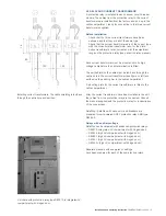
Auxiliary switches (2NO+2NC) can be supplied to indicate
switch positions on all switches. Blown fuse-link can also be
indicated by means of an auxiliary switch (1NO).
Motor operation, coils and auxiliary switches can easily be
retrofitted.
When ordered, switchgear can also be supplied with an
auxiliary switch (1NO) for monitoring of SF
6
pressure.
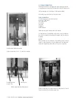
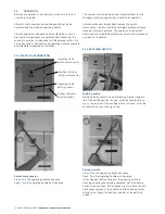
Access to the low-voltage connections is gained by removing
the top front panel.
6.2 CAPACITIVE VOLTAGE INDICATION
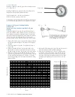
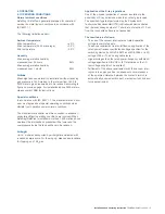
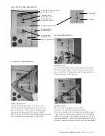
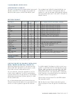
All modules can be equipped with capacitive voltage
indication type HR-module (VDS) or VPIS (Voltage Present
Indicating System) acc. to IEC 61958.
This system has integrated LEDs.
By means of the sockets in VPIS and HR it is possible to carry
out phase balance check using suitable phase comparators.
6.3 CURRENT MEASUREMENT
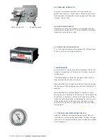
Ammeter (72 x 72 mm) and selector switch can be installed in
each module. Current transformers have to be installed inside
the cable compartment.
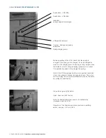
6.4 SIDE EXTENSION
When ordered, switchgear can be manufactured with side
extension on both sides. This makes the switchgear more
flexible and it can then be prepared for future extension.
For connection of switchgear, please see separate Installation
manual for side extension, VDD006146 GB
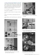
VPIS
VIM-1
VIM-3
HR-module

